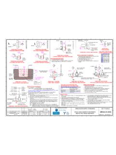
Transcription of MRWA-W-212
1 1 2 3 4 5 6 7 8 9 10 11 12. OPTIONS: . 1. For deflections past higher risk structures such as barrel drains, waterways, major roads and rail lines, welded L OFFSET = PIPE / JOINT TYPE. mains are required. Refer to MRWA-W-210 and MRWA-W-211 for details.. A A. 2. Cold bending of PVC mains is not permitted. TYPICAL TYPICAL TYPICAL PVC COMMENTS. 3. Optimise risk and construction cost by: TABLE 212-C: DEFLECTIONS RETIC PVC RETIC DI PIPE + DOUBLE. Minimizing the number of joints. Full length pipes preferred to cut pipes which if necessary should be of FIGURE 212-A: 1 PIPE DEFLECTION OFFSET SOC. PIPE PIPE. maximum possible length. CONNECTOR 6. For multiple cut pipe situations, the minimum cut pipe length is 21 normal pipe length. Minimiising the amount of excavation required. Vertical deflections over longer distances will require TYPICAL FULL LENGTH FOR L (m) 6 6 (PVC).
2 Significant extra excavation. L TYPICAL MINIMUM LENGTH FOR L (m) 3 3 (PVC). Minimising the number of concrete thrust blocks required, especially vertical thrust blocks. OFFSET = 1 7 VARIES DEPENDING ON MANUFACTURER. TYPICAL MAX (degrees). Only switching between pipe types (from RRJ main to a welded main and back again) where strictly L. necessary. MAX 1 PIPE MAX OFFSET (mm) 1 105 340 730 7 HORIZONTAL OR VERTICAL DEFLECTION. B B. 4. Bends: Usually enable longer pipe lengths to be predominantly used. Variety of angles available, providing 1 PIPE OFFSET (mm)- 1 x 21 PIPE 53 138 365 2 or 3 PIPE HORIZONTAL DEFLECTION. flexibility. MAX 2 PIPE MAX OFFSET (mm) 1 210 670 7 1460 7 USUALLY NOT PREFERRED ALONG. Enable deflections to occur over a short distance, potentially reducing excavation & disruption to other services.
3 FIGURE 212-B: 2 PIPE DEFLECTION OFFSET STRAIGHT ROADS DUE TO DISRUPTION. Socketed bends may require concrete blocking, which could be a problem in tight situations. MAX 3 PIPE MAX OFFSET (mm) 1 350 1115 7 2425 7 OF OTHER ASSETS. Often not practical in horizontal curved alignments as bends will often encroach on the alignment of neighboring 3 PIPE OFFSET (mm)- 3 x 21 PIPE 210 455 7 1212 7.. services. L TYPICAL MIN R (m)- WHOLE PIPE 344 90 49. Sockets shall be offset so that they are not directly below obstructions. TYPICAL MIN R (m)- 1/2 PIPE 172 45 25. Restrained joint vertical bends are preferred to socketed bends. OFFSET =. 5. Pipe socket deflections: Limited deflections possible. + (2 ) VERTICAL BLOCKING REQUIREMENTS NO THRUST THRUST THRUST CONTROL VERTICAL BLOCKS REQUIRE. L. Do not usually require blocking (DI pipe may at larger angles).
4 BLOCK CALCULATION REQUIRED 3 WATER AGENCY APPROVAL 5. C R C. L REQUIRED REQUIRED 2. Low joint numbers, especially with full length pipes. Vertical deflections occur over a long distance, increasing excavation. HORIZONTAL BLOCKING NO THRUST THRUST THRUST BLOCK. 6. Double socket connectors: When used in numbers with short pipes, joint numbers will be high. R REQUIREMENTS BLOCK CALCULATION REQUIRED 4. Only suitable for shorter curves / deflections. REQUIRED REQUIRED 2. Pretapped connectors are equivalent to double socket connectors in their deflection capability. 7. Change to PE: Requires specialist welding skills to construct and careful thrust restraint at ends, but may NOTES Regarding Table 212-C: significantly reduce the number of unrestrained joints, especially for long curves. R= L. 1. Max offsets calculated using full length pipes and no fittings.
5 PE shall be bent in accordance with PIPA guideline POP202. 2 TAN ( /2). 2. Thrust control requirements need to be calculated as per the method described in MRWA-W-204. L = R 2 TAN ( /2) (ie CUT PIPE LENGTH FOR REQUIRED RADIUS R). TABLE 212-A: HORIZONTAL DEVIATION PREFERENCES 3. Block as per Table 205A-A using 1 2 of the mass volume of the bend. D D. 4. Block as per 6 bends of MRWA-W-204. PREFERENCE < 4 PIPE LENGTHS > 4 PIPE LENGTHS. 5. Flanged or welded bends preferred to vertical blocks. FABRICATED BENDS, or FABRICATED BENDS (for 6. Pre-tapped connectors provide the same amount of joint deflection as a double socket connector. 1 PIPE SOCKET DEFLECTIONS multiple sharper deflections), or FIGURE 212-C: 3 PIPE DEFLECTION OFFSET or CURVED MAIN. 7. For larger defections, it is often better to use bends to reduce excavation depths and / or limit disruption to horizontal alignments.
6 2 DOUBLE SOCKET CONNECTORS, or PIPE SOCKET DEFLECTIONS. PRE-TAPPED CONNECTORS (for longer radius curves), or DI SOCKET ( 1 ). CHANGE TO PE (for shorter 3 CHANGE TO PE 1. radius curves). L1 1 = DI pipe socket angle of deflection (~ ), or HIGHER PREFERENCE OPTIONS SHALL BE USED WHENEVER PRACTICABLE. Double socket angle of deflection (~7 ). 2 OFFSET =. E TABLE 212-B: VERTICAL DEVIATION PREFERENCES 2 = PVC pipe socket angle of deflection (~1 ), or E. L2 2L1 Sin 1 + L2 Sin( 1 + 2). PREFERENCE JOINTING SYSTEM Double socket angle of deflection (~7 ). L1. UNBLOCKED PIPE SOCKET DEFLECTIONS, or 1. 1. WELDED BENDS (PE or MSCL). DI SOCKET ( 1 ). 2 FLANGED BENDS. FIGURE 212-D: 3 PIPE DEFLECTION OFFSET WITH Di AND PVC SOCKETS. HIGHER PREFERENCE OPTIONS SHALL BE USED WHENEVER PRACTICABLE. 100 MIN. F 100 350 MAX TABLE 212-D: VALVE HEIGHTS F.
7 FSL FSL FSL. MAXIMUM VALVE HEIGHT. NOMINAL. 'H' (mm). 450 DIAMETER (DN). (PER AS 2638). HEIGHT 'H'. 825 100 450. x TRENCH DEPTH 150 520. 225 660. 300. 300 825. G EXAMPLE: 375 985 G. VERTICAL OFFSET REQUIRED = VALVE HEIGHT (H) + SPINDLE COVER - 21 MAIN OD - MINIMUM PIPE COVER 450 1145. = 825 + 100 - 150 - 450 = 325 500 1270. VERTICAL DEFLECTION TO A VALVE 600 1560. 750 1900. MELBOURNE RETAIL WATER AGENCIES. DESIGNED: R. JAGGER DATE: 10/07/2011 MRWA WATER SUPPLY STANDARDS NOT TO SCALE. DRAWN: D. TOLENTINO DATE: 10/07/2011. H H. 3 MINOR ADDITIONS TO NOTES / TABLE 1/12/2016 RJ / CP / JT CHECKED: NAME DATE APPROVED: NAME DATE. 2 PUBLISHED FIRST ISSUE 23/03/12 R. JAGGER X CWW C. RIVETTE 23/03/12 X CWW R. CARRUTHERS 23/03/12 CURVES AND DEFLECTIONS MRWA-W-212 . 1 PRE PUBLISHED DRAFT FOR COMMENT 12/07/11 R. JAGGER X SEWL 23/03/12 X SEWL G.
8 REYNOLDS 23/03/12 (VERTICAL & HORIZONTAL). REV DESCRIPTION DATE APPROVED X YVW K. DAWSON 23/03/12 X YVW A COSHAM 23/03/12 ISSUED 2012 REVISION NO. 3. 1 2 3 4 5 6 7 8 9 10 11 12.