Transcription of metraonline.com
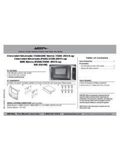
1 CAUTION! All accessories, switches, climate controls panels, and especially air bag indicator lights must be connected before cycling the ignition. Also, do not remove the factory radio with the key in the on position, or while the vehicle is running. Metra. The World s Best Kits. COPYRIGHT 2018 METRA ELECTRONICS CORPORATION REV. 5/25/18 INST99-3018 INSTALLATION INSTRUCTIONS99-3018 KIT FEATURES ISO DIN radio provision with pocket ISO DDIN radio provision 99-3018HG - gloss black, 99-3018S - silverKIT COMPONENTS A) Radio trim panel B) Radio brackets C) Pocket D) Upper dash trim panel (for navigation models) E) (2) Plastic washers F) (2) Metal clips G) (4) #8 x 3/8 Phillips truss-head screws H) (8) #8 x 3/8 Phillips pan-head screws I) (2) Copper threaded inserts J) Axxess interface and wiring harness (not shown)TOOLS REQUIRED Panel removal tool 9/32 socket wrench T-10 Torx driver Cutting tool Phillips screwdriverTABLE OF CONTENTSDash Disassembly.
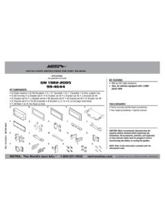
2 2-4 Kit Preparation ..5 Kit Assembly ISO DIN radio provision with pocket ..6 ISO DDIN radio provision ..6 Axxess Interface Installation ..7-15 WIRING & ANTENNA CONNECTIONS Wiring Harness: Axxess interface and harness includedAntenna Adapter: 40-EU10 (sold sep.)Steering wheel control interface: ASWC-1 (sold sep.) Backup camera retention: BACKUPCAM-2 (sold sep.)ABCHGIDEFC adillac* CTS (Coupe) 2014, CTS-V 2008-2014 CTS (Coupe/Sedan) 2008-2013* Please note this kit will not work in the Sport | Remove the left and right shifter side trim panels. (Figure A)2a. Auto transmission vehicles: Unclip the shifter trim. (Figure B) Note: The boot and knob will remain in Manual transmission vehicles: Unclip the shifter trim and pull straight up on the shift knob to remove the knob and trim as one unit.
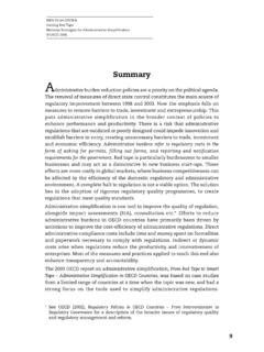
3 (Figure C) Note: This requires a lot of force, do not twist the knob or the locking tab inside the shift knob will break. Continued on the next page(Figure B)(Figure A)(Figure C)DASH DISASSEMBLYREV. 5/25/2018 INST99-301833. Remove the dash trim on both sides of the radio panel. (Figures D, E)4. Unclip the top dash radio trim (non-navigation models only). (Figure F) Note: There will be a strap connected to this panel that cannot be removed until step 5 is performed. After step 5, remove (1) 9/32 screw securing the strap and then remove the panel. Continued on the next pageDASH DISASSEMBLY (CONT.)(Figure E)(Figure D)(Figure F) | DISASSEMBLY (CONT.)Unless otherwise stated, ensure that the vehicle is completely off before proceeding onto the following steps: 5.
4 Remove (2) 9/32 screws from the bottom of the radio/climate control panel and unplug & remove the panel (Figure G) (WARNING!!! Do not unplug the panel if the vehicle has factory navigation, continue to step 6).6. Navigation models only: With the radio/climate control panel still connected, cycle the key to accessory, and then press the button on the upper left of the panel to raise the navigation screen. Remove (3) 9/32 screws holding the screen into the dash, unplug and remove the screen, turn the key to the off position, and then remove the key from the ignition. Now it is safe to unplug and remove the radio/climate control panel. (Figure H) Note: Failure to follow this step properly will result in the airbag light illuminating in the instrument cluster.
5 7. Remove (4) 9/32 screws from the radio chassis, and then unplug and remove the radio chassis from the dash. (Figure I) Continue to Kit Preparation(Figure I)(Figure G)(Figure H)REV. 5/25/2018 INST99-30185 KIT PREPARATION1. Remove (4) Phillips screws to remove the ashtray/pocket from the bottom of the radio/climate control panel. (Figure A)2. Remove (4) T-10 Torx screws and (16) Phillips screws to remove the radio/climate controls, and radio/climate bezel from the panel. (Figure B) Note: The radio/climate bezel will not be used in this Remove (4) Phillips screws to remove the upper screen trim Cut the radio/climate control panel clock support area as shown in the diagram. (Figure C) Note: Vent removal is Using either the factory hardware or the (8) #8 x 3/8 Phillips pan-head screws provided, secure the 99-3018 radio trim panel and factory components to the modified factory panel.
6 (Figure D and E) 6. Use the (2) supplied plastic washers on the top two mounting positions. (Figure F)7. Connect the left and right climate control connectors to the radio/climate control panel. (Figure G) Continue to Kit Assembly(Figure A)(Figure E)(Figure D)(Figure B)(Figure F)(Figure C)(Figure G)Remove shaded | ASSEMBLYISO DIN radio provision with pocket1. Secure the radio brackets to the pocket using the (4) #8 x 3/8 Phillips screws provided. (Figure A)2. Remove the metal DIN sleeve and trim ring from the aftermarket Slide the radio into the bracket/pocket assembly, then secure it using the screws supplied with the radio. (Figure B) Continue to Axxess Interface InstallationISO DDIN radio provision 1.
7 Secure the radio brackets to the radio using the screws supplied with the radio. (Figure A) Continue to Axxess Interface Installation(Figure A)(Figure A)(Figure B)REV. 5/25/2018 INST99-30187 AXXESS INTERFACE INSTALLATIONINTERFACE FEATURESINTERFACE COMPONENTS Axxess interface 3018 harness 16-pin harness with stripped leads 4-pin to 4-pin resistor pad harnessTOOLS REQUIRED Crimping tool and connectors, or solder gun, solder, and heat shrink Small flat blade screwdriver Tape Wire cutter Zip tiesTABLE OF CONTENTSC onnections to be made ..8-13 For models without an amplifier ..8-9 For models with an analog amplifier ..10-11 For models with a digital amplifier ..12-13 Installing the Axxess interface.
8 13 Programming the Axxess interface ..14 Adjusting the Axxess interface ..14 Final assembly ..15 Troubleshooting ..15 Provides accessory power (12-volt 10-amp) Maintains the Retained Accessory Power ( ) feature Provides NAV outputs (parking brake, reverse, speed sense) Retains warning chimes Retains OnStar/OE Bluetooth Adjustable volume for chimes and OnStar Retains the factory AUX-IN jack Pre-wired ASWC-1 harness (ASWC-1 sold separately) Can be used in non-amplified, or analog/digital amplified models* Retains balance and fade Micro B USB updatable* Please reference the Service Parts Identification sticker located under the spare tire cover. If the RPO code UQA is listed, then the vehicle is equipped with an analog DELCO amplifier.
9 If the RPO code UQS is listed, then the vehicle is equipped with a digital BOSE amplifier. Excluding digital amplified | TO BE MADE Connect the Green/Purple wire to the reverse wire. Connect the Light Green wire to the parking brake wire. Tape off and disregard the following (5) wires, they will not be used in this application: Blue/White, Purple, Purple/Black, Green, Green/BlackFrom the 3018 harness to the aftermarket radio: Connect the Black wire to the ground wire. Connect the Yellow wire to the battery wire. If installing either an ASWC-1 or AX-LCD (both sold separately), connect the (2) Red wires to accessory power. Cut off and remove the resistors from the Green, Green/Black, Purple, and Purple/Black wires below the heat shrink.
10 Connect the Green wire to the left rear positive speaker output. Connect the Green/Black wire to the left rear negative speaker output. Connect the Purple wire to the right rear positive speaker output. Connect the Purple/Black wire to the right rear negative speaker output. Ensure the (2) 4-pin Molex connectors are connected together. Note: The 4-pin to 4-pin resistor pad harness will not be used in this application. Continued on the next pageAttention! This interface will work with models that are either non-amplified, analog amplified, or digital amplified. Please follow the instructions carefully for your model vehicle. Failure to do so will result in either no sound, or low sound.