Transcription of Model 77 Series IV - Fluke Corporation
1 Model 77 Series IV Digital Multimeter Users Manual PN 2695884 September 2006 2006 Fluke Corporation . All rights reserved. Printed in USA All product names are trademarks of their respective companies. Lifetime Limited Warranty Each Fluke 20, 70, 80, 170 and 180 Series DMM will be free from defects in material and workmanship for its lifetime. As used herein, life-time is defined as seven years after Fluke discontinues manufacturing the product, but the warranty period shall be at least ten years from the date of purchase. This warranty does not cover fuses, disposable batteries, damage from neglect, misuse, contamination, alteration, accident or abnormal conditions of operation or handling, including failures caused by use outside of the product s specifications, or normal wear and tear of mechanical components. This warranty covers the original purchaser only and is not transferable.
2 For ten years from the date of purchase, this warranty also covers the LCD. Thereafter, for the lifetime of the DMM, Fluke will replace the LCD for a fee based on then current component acquisition costs. To establish original ownership and prove date of purchase, please complete and return the registration card accompanying the product, or register your product on Fluke will, at its option, repair at no charge, replace or refund the purchase price of a defective product purchased through a Fluke authorized sales outlet and at the applicable international price. Fluke reserves the right to charge for importation costs of repair/replacement parts if the product purchased in one country is sent for repair elsewhere. If the product is defective, contact your nearest Fluke authorized service center to obtain return authorization information, then send the product to that service center, with a description of the difficulty, postage and insurance prepaid (FOB Destination).
3 Fluke assumes no risk for damage in transit. Fluke will pay return transportation for product repaired or replaced in-warranty. Before making any non-warranty re-pair, Fluke will estimate cost and obtain authorization, then invoice you for repair and return transportation. THIS WARRANTY IS YOUR ONLY REMEDY. NO OTHER WARRANTIES, SUCH AS FITNESS FOR A PARTICULAR PURPOSE, ARE EXPRESSED OR IMPLIED. Fluke SHALL NOT BE LIABLE FOR ANY SPECIAL, INDIRECT, INCIDENTAL OR CONSEQUENTIAL DAM-AGES OR LOSSES, INCLUDING LOSS OF DATA, ARISING FROM ANY CAUSE OR THEORY. AUTHORIZED RESELLERS ARE NOT AUTHORIZED TO EXTEND ANY DIFFERENT WARRANTY ON Fluke S BEHALF. Since some states do not allow the exclusion or limita-tion of an implied warranty or of incidental or consequential damages, this limitation of liability may not apply to you. If any provision of this warranty is held invalid or unenforceable by a court or other decision-maker of competent jurisdiction, such holding will not affect the validity or enforceability of any other provision.
4 Fluke Corporation Fluke Europe Box 9090 Box 1186 Everett, WA 98206-9090 5602 BD Eindhoven The Netherlands Visit the Fluke website at: Register your Meter at: 2/02 i Table of Contents Title Page Contacting Fluke .. 1 Warning and Caution 1 Unsafe Voltage .. 1 Test Lead Alert .. 1 Battery Saver (Sleep Mode) .. 2 Terminals .. 2 Rotary Switch Positions .. 2 Display .. 3 MIN MAX AVG Recording Mode .. 4 AutoHOLD 4 YELLOW Button .. 4 Display Backlight.
5 4 Manual Ranging and Autoranging .. 5 Power-Up Options .. 5 Making Basic Measurements .. 6 Measuring AC and DC Voltage .. 6 Measuring Resistance .. 6 Measuring Capacitance .. 6 Testing for Testing 7 Measuring AC or DC Current .. 8 Measuring Frequency .. 8 Using the Bar Graph .. 9 9 Testing the Fuses .. 9 Replacing the Battery and Fuses .. 10 11 ii XWWarning. Read before using the Meter To avoid possible electrical shock or personal injury, follow these guidelines: Use the Meter only as specified in this manual or the protection provided by the Meter might be impaired. Do not use the Meter or test leads if they appear damaged, or if the Meter is not operating properly. If in doubt, have the Meter serviced. Always use the proper terminals, switch position, and range for measurements. Verify the Meter's operation by measuring a known voltage.
6 Do not apply more than the rated voltage, as marked on the Meter, between the terminals or between any terminal and earth ground. Use caution with voltages above 30 V ac rms, 42 V ac peak, or 60 V dc. These voltages pose a shock hazard. Disconnect circuit power and discharge all high-voltage capacitors before testing resistance, continuity, diodes, or capacitance. Do not use the Meter around explosive gas or vapor. When using the test leads, keep your fingers behind the finger guards. Remove test leads from the Meter before opening the Meter case or battery door. Symbols B AC (Alternating Current) I Fuse F DC (Direct Current) P Conforms to European Union directives F B DC/AC $ Canadian Standards Association J Earth ground T Double insulated W Important Information; see manual X Hazardous Voltage b Battery (Low battery when shown on display) !
7 Underwriters Laboratories, Inc. Meter in accordance with IEC 61010-1. 54CJ s Inspected and licensed by T V (Technischer berwachungs Verein) Product Services ; N10140 Conforms to relevant Australian standards # VDE (Verband Deutscher Electroniker) 1 Model 77 Series IV Digital MultimeterThe Fluke Model 77 Series IV is a battery-powered, average responding-rms indicating multimeter (hereafter "the Meter"), with a 6000-count, 3 3/4-digit display, and a bar graph. This meter meets CAT III and CAT IV IEC 61010 standards. The IEC 61010 safety standard defines four measurement categories (CAT I to IV) based on the magnitude of danger from transient impulses. CAT III meters are designed to protect against transients in fixed-equipment installations at the distribution level; CAT IV meters are designed to protect against transients from the primary supply level (overhead or underground utility service).
8 The Meter measures or tests the following: AC / DC voltage & current Diodes Resistance Continuity Voltage frequency Capacitance Contacting Fluke To contact Fluke , call: 1-888-993-5853 in USA 1-800-363-5853 in Canada +31 402-675-200 in Europe +81-3-3434-0181 in Japan +65-738-5655 in Singapore +1-425-446-5500 from anywhere in the world Visit Fluke 's web site at: Register your Meter at: Warning and Caution Statements A XWWarning identifies hazardous conditions and actions that could cause bodily harm or death. A Caution identifies conditions and actions that could damage the Meter, the equipment under test, or cause permanent loss of data. Unsafe Voltage To alert you to the presence of a potentially hazardous voltage, when the Meter detects a voltage 30 V or a voltage overload (OL), the Ysymbol is displayed. Test Lead Alert To remind you to check that the test leads are in the correct terminals, LEAd is momentarily displayed when you move the rotary switch to or from the mA or A position.
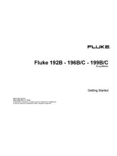
9 W Warning Attempting to make a measurement with a test lead in an incorrect terminal might blow a fuse, damage the Meter, and cause serious personal injury. Model 77 Series IV Users Manual 2 Battery Saver (Sleep Mode) The Meter enters the "Sleep" mode and blanks out the display if there is no function change or button press for 20 minutes. To disable the Sleep mode, hold down the yellow button while turning the Meter on. The Sleep mode is always disabled in the MIN MAX AVG mode and the AutoHOLD mode. Terminals . Item Description 1 Input terminal for AC and DC milliamp measurements to 400 mA. 2 Input terminal for AC and DC current measurements to 10 A. 3 Input terminal for voltage, continuity, resistance, diode test, capacitance, and frequency measurements. 4 Common (return) terminal for all measurements.
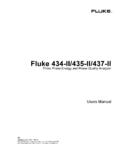
10 Rotary Switch Positions Switch PositionMeasurement Function K Hz AC voltage from to 1000 V. Frequency from 2 Hz to kHz. L DC voltage from 1 mV to 1000 V. mL DC mV from mV to 600 mV. e E Ohms from to 50 M . Farads from 1 nF to 9999 F. R G Beeper turns on at <25 and turns off at >250 . Diode test. Displays OL above V. FB mA AC mA from mA to 400 mA. DC mA from mA to 400 mA. F BA AC A from A to 10 A. DC A from A to 10 A > display flashes. >20 A, OL is displayed. Display 3 Display . No. Symbol Meaning 1 s Continuity test.