Transcription of Model PRV-1 Pressure Reducing Valve Pilot …
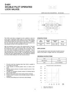
1 Worldwide PRV-1 Pressure Reducing Valve Pilot operated , Globe and Angle Body StylesPage 1 of 16 MARCH 2015 TFP1580 Worldwide applications Within the main header (Ref. Figure 1) supplying wet pipe, dry pipe, deluge, or preaction system risers, and/or a standpipe system supplying hose connections As part of a sectional floor control assembly (Ref. Figure 2) supply-ing sprinkler systems, and/or hose stationsFeatures Can be installed in vertical or hori-zontal orientation Eliminates any required bleeding of trapped air from the diaphragm chamber during installation Globe or angle pattern Accurate Pressure control Standard nylon coated internal and external One piece, one moving part diaphragm In-line service One Pilot Valve sub-assembly pro-vides for any outlet set Pressure , that is, 80 to 225 psi (5,5 to 15,5 bar)
2 NOTICEThe TYCO Model PRV-1 Pressure Reducing Valves described herein must be installed and maintained in compli-ance with this document and with the applicable standards of the National Fire Protection Association, in addi-tion to the standards of any authorities having jurisdiction. Failure to do so may impair the performance of these are responsible for maintaining their fire protection system and devices in proper operating condition. Contact the installing contractor or sprinkler manufacturer with any to the flow regulating characteris-tic of this device, its impact on system hydraulics should be carefully consid-ered, especially when retrofitted into existing of the Needle Valve is factory set and must not be DescriptionThe TYCO Model PRV-1 Pressure Reducing Valves, 2 through 8 Inch (DN50 through DN200), are factory-assembled and fully trimmed Valve arrangements for Pressure control.
3 They are used on water filled pipe where it is necessary to reduce a higher inlet Pressure to a lower delivery Pressure under static and/or residual flowing conditions. The Model PRV-1 Valve is intended to automatically main-tain the outlet set Pressure (static and residual) within a close range, regard-less of fluctuations in the higher pres-sure inlet line or varying flow Model PRV-1 Valve is provided with a factory outlet set Pressure of 125 psi (8,6 bar); however, it may be field set to a nominal outlet set Pressure of 80 to 225 psi (5,5 to 15,5 bar) per its FM Approval or 80 to 150 psi (5,5 to 10,3 bar) per its UL 2 of 16 Technical DataApprovalsUL and C-UL ListedFM ApprovedThe UL Listing is based on: Installation requirements referenced in the Standard for Installation of Sprinkler Systems, NFPA 13, or the Standard for Installation of Standpipe and Hose Valves, NFPA 14, as applicable.
4 Inspection, testing, and mainte-nance requirements referenced in the Standard for Inspection, Testing, and Maintenance of Water-Based Fire Protection Systems, NFPA 25. Filed-setting of the Model PRV-1 Valve to provide required outlet pressures and flows for the given application. Testing of the Model PRV-1 Valve after installation in accordance with NFPA 13 and/or NFPA 14 as applicable. Testing the Model PRV-1 Valve tested periodically thereafter in accordance with NFPA Inlet Pressure250 psi (17,2 bar)Factory Outlet Set Pressure 125 psi (8,6 bar)Field Outlet Set Pressure Range80 to 225 psi (5,5 to 15,5 bar) per FM Approval, or 80 to 150 psi (5,5 to 10,3 bar) per UL ListingPressure Loss With Inlet Pressure Above Set Pressure The inlet Pressure minus the outlet set Pressure equals Pressure loss.
5 For example, assuming that the inlet flowing Pressure is 225 psi (15,5 bar) and the field outlet set Pressure is 130 psi (9,0 bar), the Pressure loss is 95 psi (6,5 bar). Pressure Loss with Inlet Pressure Below Set Pressure Refer to Graphs A through E. (These graphs are a requirement of UL and should be used as reference only.)Rated Flowing Range2 inch ..0 to 250 GPM(DN50) .. (0 to 946 LPM)3 inch ..0 to 550 GPM(DN80) ..(0 to 2080 LPM)4 inch ..0 to 1000 GPM(DN100) ..(0 to 3785 LPM)6 inch ..0 to 2200 GPM(DN150) ..(0 to 8325 LPM)8 inch ..0 to 4000 GPM(DN200) ..(0 to 15140 LPM)End Connections Threaded end connections are avail-able as NPT threaded or threaded per ISO 7-1. Flanged end connections are avail-able as drilled per Table C.
6 Grooved end connections fol-low industry standard groove VALVERELIEF VALVEZRISERMANIFOLDORZONECHECKSPRINKLERS CHECKVALVESECTIONALCONTROLVALVECHECKVALV EMAINHEADERPRV-1 HOSESTATIONSMAINDRAINDRY PIPESPRINKLERRISERWET PIPESPRINKLERRISERMAINCONTROLVALVEMAINDR AINPRV-1 MAINCONTROLVALVERELIEFVALVEFIGURE 2 TYPICAL SECTIONAL FLOOR CONTROL APPLICATIONFIGURE 1 TYPICAL MAIN HEADER APPLICATIONTFP1580 Page 3 of 16 Body StyleEnd ConnectionNominal Valve Size2 Inch (DN50)3 Inch (DN80)4 Inch (DN100)6 Inch (DN150)8 Inch (DN200)GlobeThread x Thread N/AN/AN/AN/AGroove x Groove N/AFlange x FlangeN/AN/A = Available N/A = Not AvailableBody StyleEnd ConnectionNominal Valve Size2 Inch (DN50)3 Inch (DN80)4 Inch (DN100)6 Inch (DN150)8 Inch (DN200)GlobeThread x Thread N/AN/AN/AGroove x Groove N/AFlange x FlangeN/A AngleThread x Thread N/AN/AN/AGroove x Groove N/AFlange x FlangeN/A N/A = Available N/A = Not AvailableNominal Valve Size Inches (DN)Flange Drilling SpecificationNominal Dimensions in Inches and (mm)ANSI (1) (Class 125)ISO 7005-2 (PN10)(2)ISO 7005-2 (PN16)(3)JIS B 2210 (10K)AS 2129 ( Table E)ABNABNABNABNABN3(80) (152,4) (19,0)4 USE ISO 7005-2 (PN16) (160,0) (19,0)8N/AN/A4(100)7.
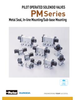
7 5 0 (190,5) (19,0)87. 0 9 (180,0) (19,0) (175,0) (15,0)87. 0 0 (178,0) (18,0)86(150) (241,3) (22,2) (240,0) (23,0) (240,0) (19,0) (235,0) (22,0)88(200) (298,5) (22,2) (295,0) (23,0) (295,0) (23,0)12N/A11. 5 0 (292,0) (22,0)8 NOTES1. Same drilling as for ANSI (Class 150) and ANSI (Class 150)2. Same drilling as for BS 4504 Section (PN10) and DIN 2532 (PN10)3. Same drilling as for BS 4504 Section (PN16) and DIN 2532 (PN16)Dim. ABolt CircleDiameterDim. BBolt HoleDiameterQty. NNumber ofBolt HolesTABLE A AVAILABLE SIZES AND CONFIGURATIONS NORTH AMERICATABLE B AVAILABLE SIZES AND CONFIGURATIONS SOUTH AND CENTRAL AMERICA AND EASTERN HEMISPHERETABLE C DIMENSIONAL SPECIFICATION FOR SELECTION OF FLANGE DRILLINGTFP1580 Page 4 of ..634521(a)7(b)8(c)9(d)(f)1011(e)12(g)KI TDESCRIPTIOND iaphragmHex Bolt,6 Inch Valve , M16 x 453 & 4 Inch Valves,6 & 8 Inch Valves, M168 Inch Valve , M16 x 55M16 x 552 Inch Valve , M12 x 35 Diaphragm CoverFlat Washer,2 Inch Valve , M123 & 4 Inch Valves, M16 Valve BodyHex Nut, M16,4 Inch Valve PARTSNRCHCHCH(a)NRCHCHD iaphragm,REPLACEMENT PART KITS2 Inch Valves3 Inch Valves4 Inch Valves8 Inch Valves6 Inch ValvesDESCRIPTIONKIT92-570-2-01192-570-2 -01292-570-2-01392-570-2-01592-570-2-014 P/NPilot Valve (c) Pilot Valve92-570-2-200 Water Pressure Gauge(d)Water Pressure Gauge92-570-2-211 Strainer(e)Strainer:92-570-2-202 Tubing and Fitting Kit, Pressure Sensor Insert(f)Excludes Items 7, 8, 9, 10 and 12 Globe Style Valve .
8 2 Inch Valve92-570-3-00192-570-3-00492-570-3-00 592-570-3-00392-570-3-0028 Inch Valve6 Inch Valve4 Inch Valve3 Inch Valve2 Inch Valve6 Inch Valve4 Inch Valve3 Inch ValveAngle Style Valve :Fits Either Body Style,Includes Item 2 only:Tubing and FittingsPressure Sensor Insert:92-571-3-00492-571-3-00392-571-3- 00292-571-3-00192-570-2-20492-570-2-2059 2-570-2-20792-570-2-20692-570-2-2033 Inch Valve4 Inch Valve6 Inch Valve8 Inch Valve2 Inch Valve2, 3, & 4 Inch Valves6 & 8 Inch Valves92-570-2-209(b)NOTES:NR - Not ReplaceableCH - Common Item 8 in Valve (g)Needle Valve92-570-2-21234, 5, 6881817112118911111110121274, 5, 632 ANGLE BODY STYLEGLOBE BODY STYLEANGLEGLOBESTRAINERDETAILPRESSURE SENSORINSERT DETAILINLETPRESSUREGAUGEINLETPRESSUREGAU GEOUTLETPRESSUREGAUGEDIAPHRAGMCHAMBERSTR AINER(SEE DETAIL)STRAINER(SEE DETAIL)PRESSURESENSOR INSERT(SEE DETAIL)PRESSURESENSOR INSERT(SEE DETAIL)UPSTREAMINLETCAVITYDOWNSTREAMOUTL ETCAVITYDOWNSTREAMOUTLETCAVITYUPSTREAMIN LETCAVITYOUTLETPRESSUREGAUGEORIENTDIAPHR AGM TABPERPENDICULARTO OUTLETOUTLETOUTLETSENSORINLET FACESDOWNSTREAMINLET CAVITYINTERIOROUTLET CAVITYINTERIORDIAPHRAGMCHAMBERFIGURE 3 Model PRV-1 Pressure Reducing Valve ASSEMBLYTFP1580 Page 5 of 16 Materials of Construction(Refer to Figure 3)
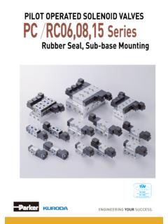
9 The Body is RILSAN polyamide 11 coated, ductile iron per ASTM A 536-77, Grade 65-45-12. The Diaphragm Cover is RILSAN polyamide 11 coated, ductile iron per ASTM A 536-77, Grade 65-45-12. The Diaphragm is nylon fabric-rein-forced, natural rubber per ASTM D2000. Diaphragm Cover Fasteners are galvanized carbon steel. The Pilot Valve is brass and stain-less steel with nylon fabric-rein-forced, natural rubber per ASTM D 2000 diaphragm. The Strainer is brass and stainless steel. Pressure Gauges have a 2-1/2 inch (65 mm) diameter, stainless steel case, and 0 to 350 psi (25 bar) pres-sure rating. Tube, Fittings, and Needle Valve are copper, brass, and stainless reference to Figure 4, the system water supply Pressure from the inlet cavity of the Model PRV-1 Valve enters the Diaphragm Chamber through a Strainer and Needle Valve .
10 The factory set Needle Valve provides the required orifice size for the supply line to the Diaphragm Chamber to optimize flow from the Diaphragm Chamber through the Pilot Valve is controlled by a regulating spring that is factory set, and subsequently field adjustable, to the desired downstream set Pressure that is to be maintained. A sensing line connects the outlet of the Pilot Valve to the system piping downstream of the Model PRV-1 Valve via the Pressure Sensor Insert in the outlet the downstream Pressure rises above the set Pressure of the spring, exit flow from the Diaphragm Chamber through the Pilot Valve to the Model PRV-1 Valve outlet cavity is stopped and Pressure increases in the Diaphragm Chamber.