Transcription of MODELS: YHJF18 THRU 60 - UPGNET
1 TECHNICAL GUIDELX SERIESSPLIT-SYSTEM HEAT SEER R-410A 1 THRU 5 NOMINAL TONSMODELS: YHJF18 THRU 60 Due to continuous product improvement, specificationsare subject to change without us on the web at and rating information can be found at SUMMARY*Extended 10-Years limited parts 10-Years limited compressor 10-Years limited parts warranty requires onlineregistration within 90 days of purchase for replacement orclosing for new home construction.*Does not apply to R-22 models, 3-Phase models, or internet Limited Warranty certificate in User's Information Manual for details.
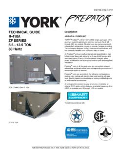
2 561923-YTG-F-0114 FOR DISTRIBUTION USE ONLY - NOT TO BE USED AT POINT OF RETAIL SALEDESCRIPTIONThe SEER Series unit is the outdoor part of a versatile cli-mate system. It is designed with a matching indoor coil compo-nent from Johnson Controls Unitary Products. Available fortypical applications this climate system is supported with acces-sories and documents to serve specific Small Footprint - The compact footprint is a perfect fit forany application. Quality Condenser Coils - The coil is constructed of coppertubing and enhanced aluminum fins for increased perfor-mance.
3 Coil Protection - Coils are protected from damage by a slot-ted, stamped steel coil guard. Protected Compressor - Compressors are protected inter-nally by a high pressure relief valve and a temperature sen-sor, and externally by the system high and low pressureswitches. A factory installed liquid line filter-drier further pro-tects the compressor against moisture and debris. The 5-tonsystem utilizes a two-stage compressor. Environmentally Friendly Refrigerant - The next genera-tion refrigerant R-410A delivers environmentally friendly per-formance with zero ozone depletion.
4 Durable Finish - The cabinet is made of G90-equivalent pre-painted steel, with special primer formulas and matte cham-pagne texture to insure less fading when exposed to sun-light. The coated steel wire fan guard and pre-treated,galvanized steel chassis components resist corrosion andrust creep. Lower Installed Cost - Installation time and costs arereduced by easy power and control wiring connections. Theunit is factory charged for a 15-foot lineset. The small basedimension means less space is required on the ground orroof. Top Discharge - Warm air from the top mounted fan is blownup, away from the structure and any landscaping.
5 This allowscompact location on multi-unit applications. Quiet Operation - The compressor sound blanket and theswept wing fan blade keep sound to a minimum. The upwardair flow carries the normal operating noise away from the liv-ing area. The rigid top panel effectively isolates any motorsound. Isolator mounted compressor and the condenser coilmuffle the normal fan motor and compressor operatingsounds. Low Maintenance - Long life, permanently lubricated motor-bearings need no annual servicing. Easy Service Access - Fully exposed refrigerant connec-tions and a single panel covering the electrical controls makefor easy servicing of the unit.
6 Secured Service Valves - Secured, re-usable servicevalves are provided on both the liquid and vapor sweat con-nections for ease of evacuating and charging. Advanced System Control - These heat pumps feature ademand-defrost control system to provide optimal comfortand reliable operation over a wide range of conditions. Agency Listed - Safety certified by CSA to UL 1995 / Performance certified to ANSI/AHRI Standard 210/240in accordance with the Unitary Small Equipment Controls Unitary Products* Adapter Fitting Required for 1-1/8" dimensions are in inches and are subject to change without height is from bottom of base pan to top of fan length and width include screw and Electrical DataMODELYHJF18S41S1 YHJF24S41S1 YHJF30S41S1 YHJF36S41S4 YHJF42S41S5 YHJF48S41S5 YHJF60S41S1 Unit Supply Voltage208-230V.
7 1 60 HzNormal Voltage Range 1187 to 252 Minimum Circuit Overcurrent Device Amps 220303030405060 Min. Overcurrent Device Amps 315202020253040 Compressor Type ScrollScrollScrollRecipScrollScroll2-Sta ge ScrollCompressor AmpsRated HeaterNoNoNoYe sNoNoNoFactory External Discharge MufflerYe sYe sYe sCombinedDM/CVYe sYe sYe sFactory External Check ValveNoNoNoNoNoNoHS Kit Required with TXV 4 NoNoNoYe sNoNoNoFan Motor AmpsRated Load24222424242424 Fan Diameter Inches1/101/81/41/41/41/41/4 Fan MotorRated RPM8251075850850850850850 Nominal CFM2000200039003800360035003800 CoilFace Area Sq. Deep1111122 Fins / Inch22222222221818 Liquid Line Set OD (Field Installed)3/83/83/83/83/83/83/8 Vapor Line Set OD (Field Installed)3/43/43/43/47/87/81-1/8 Unit Charge (Lbs.)
8 - Oz.) 56 - 157 - 149 - 1410 - 611 - 413 - 114 - 2 Charge Per Foot, Weight Rated in accordance with AHRI Standard 110-2012, utilization range A .2. Dual element fuses or HACR circuit breaker. Maximum allowable overcurrent Dual element fuses or HACR circuit breaker. Minimum recommended overcurrent See Hard Start Kit Accessory Installation Manual for Hard Start Kit part number for each model . 5. The Unit Charge is correct for the outdoor unit, smallest matched indoor unit, and 15 feet of refrigerant tubing. For tubing lengths other than 15 feet, add or sub-tract the amount of refrigerant, using the difference in length multiplied by the per foot (Inches)Refrigerant ConnectionService Valve SizeABCL iquidVapor1828-1/43434 3/8 3/42440-1/429-1/229-1/23040-1/434343640- 1/434344240-1/43434 7/84840-1/434346040-1/434347/8 *561923-YTG-F-0114 Johnson Controls Unitary Products3 PROCEDURES:1.
9 Unit factory charge listed on the unit nameplate includes refrigerant for the outdoor unit, the smallest matched indoor unit, and 15 feet of interconnecting line Verify the TXV or orifice and additional charge required for specific matched indoor unit in the system using the above Add additional charge for the amount of interconnecting line tubing greater than 15 feet at the rate specified in Physical and Electrical Data For indoor matches requiring additional charge, the refrigerant needs to be weighed in for specific matched indoor unit and lineset Permanently mark the unit nameplate with the total system charge.
10 Total System Charge = Base Charge (as shipped) + charge adder for matched indoor unit + charge adder for line Charge for Various Matched SystemsOutdoor Unit YHJF18S41S1 YHJF24S41S1 YHJF30S41S1 YHJF36S41S4 YHJF42S41S5 YHJF48S41S5 YHJF60S41S1 Required Orifice or TXV 1, Unit 3,4,5 Additional Charge, / TXV + / TXV + 0 / TXV + / TXV + 0 AHE36C .063 / TXV + / TXV + 0 AHE42D .071 / TXV + 5 AHE48D .071 / TXV + / TXV + 0 TXV + 0 AHE60D TXV + 8 TXV + 10 TXV + / TXV + / TXV + 0 AHR36B .063 / TXV + / TXV + 0 AHR42C .071 / TXV + 5 AHR48D.