Transcription of Module 5: Substation overview
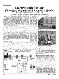
1 Course Outline to WECC of Electricity System overview of Generation overview Transmission Protection of System Operation overview Purpose of substations Substation Equipment Substation Control House Substation Bus Configurations Purpose of substations In general, a Substation is a power system facility that contains power system components such as: circuit breakers and other switchgear transformers reactors capacitors A Substation usually includes a control house that contains equipment such as: protective relays meters alarm annunciators communications equipment Purpose of substations An indoor Substation houses all electrical equipment within the walls of a building. Indoor substations may either be entirely underground or look similar to other buildings in the neighborhoods that they serve. Purpose of substations Purpose of substations Outdoor substations have the same equipment as indoor substations but the equipment is located outside where it is exposed to natural elements, rather than in a building.
2 The equipment is usually enclosed within a fence. Purpose of substations Purpose of substations Purpose of substations Ground Mat substations usually include a ground mat. A ground mat is a system of bare conductors, on or below the surface, connected to a ground to provide protection from high voltages. Purpose of substations One purpose of a Substation is to contain the equipment for changing electric energy from one voltage to another. substations also enable one or more of the following functions to be accomplished: Switching operations substations connect or disconnect elements of the power system, using circuit breakers and/or switches. Purpose of substations Reactive power compensation Utilities install synchronous condensers, shunt reactors, shunt capacitors, and static VAR compensators at substations to control voltage. Utilities install series capacitors at substations to reduce line reactance. Purpose of substations Substation Equipment In this section we describe the function and operating principles of the following power system components: Switchgear Equipment Capacitors Reactors Ground Switches Lightning Arresters Wave Traps Switchgear Switchgear is a general term given to switching and interrupting devices.
3 Switchgear equipment is commonly contained in metal-enclosed units. However, at higher voltages, the equipment may or may not be in metal enclosed units. Switchgear equipment performs two separate functions. Under normal conditions, switchgear equipment enables routine switching operations to occur. For example: Switchgear equipment disconnects and isolates a piece of equipment so maintenance work can be performed. Under abnormal conditions, switchgear equipment automatically disconnects faulted equipment from the rest of the power system as soon as possible, in order to minimize damage. Under these conditions, switchgear equipment performs a protective function. Switchgear All switchgear operates by pulling apart electric conductors (contacts). As the contacts are drawn apart while power is flowing through the device, an arc forms between the contacts. The arc is drawn out in length as the contacts open. To interrupt current flow, the arc must be extinguished with a dielectric substance, such as air, oil, or sulfur hexafluoride (SF6).
4 Switchgear We discuss the following types of switchgear equipment: Circuit Breakers Load Break Switches Disconnect Switches We examine the function and operating principle for each of these. Switchgear Circuit Breakers Circuit breakers disconnect circuits or equipment from the power system. A circuit breaker's primary function is to interrupt current flow under load or fault conditions. Circuit breakers rapidly isolate faulted portions of the power system. They also provide a means to carry out routine switching operations, such as disconnecting a device to conduct maintenance. To interrupt the current, the circuit breaker must trip. Let's examine the mechanics involved in tripping circuit breakers under fault conditions. When a fault occurs, relays sense the fault and initiate the opening of the circuit breakers related to the faulted equipment by energizing the circuit breakers' trip coils. Module 8: System Protection, presents the details on the operation of relays.
5 Circuit Breaker Operating Principles The circuit breakers open for a pre-determined time period based on the reclosing relays settings. After the pre-determined time period, the reclosing relays signal the close coils to close the circuit breakers. The time delay is sufficient to allow the arc to extinguish. If the fault still exists after reclosing ( , if it is a permanent fault, such as a conductor touching the ground), then the relays signal the circuit breakers' trip coils to open the circuit breakers again, this time permanently. Note: Not all circuit relay schemes include reclosing relays. Circuit Breaker Operating Principles Insulating Oil How an Oil Breaker Works Circuit Breaker Operating Principles Restriking The insulating medium (oil, air, etc.) is still hot from the original arc and includes ionized molecules that form a conducting path. Therefore, when the voltage increases again, the arc usually re-ignites in an action called restriking.
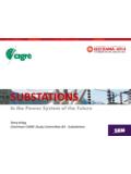
6 During restriking, the cross head continues to separate from the contacts. This process repeats itself twice per cycle until the cross head is far enough from the contacts that the arc cannot re-establish itself. At this point, the flow of current is completely interrupted. Crosshead and Contacts Open Contacts on 115kV CB Interrupting Device with new Contact Rod Receptacle installed Operating Rod (Movable Member) New Contact Rod installed Side Plate (Cross member) Crosshead and Contacts Burnt Contacts from 115kV OCB Location of Contact Rod Receptacle inside Interrupting Device 115kV OCB Operator Once the fault has been cleared, the circuit breaker can be closed. The device used to close a circuit breaker is called an operator. The methods of closing a circuit breaker are: An energized solenoid drives the breaker into the closed position. A motor compresses a closing spring that closes the breaker. Compressed air drives a piston that drives the breaker to the closed position.
7 If pressure is lost, only the pneumatic operator closing the breaker is affected; the circuit breaker's tripping or interrupting capability is not affected. Pneumatic Operating Mechanism Air compressor Compressed Air Tank Pressure Switches Air pressure gauge Compressor run time meter Pressure Regulator Drain valve Hydraulic Operating Mechanism Nitrogen fill valve for accumulator tank Accumulator tank with bladder Hydraulic Fluid Reservoir Hydraulic fluid sight glass Hydraulic pump motor Closing Spring Pressure Gauge Hydraulic Piston SOLENOID MECHANISM Operating Rod Coil AB contact linkage Plunger located behind here Operator Some circuit breakers are equipped with a switch to manually trip in the event of a failure in the electrical controls. Such switches commonly need to be manually reset before the affected circuit breaker can be closed again. A common problem that results in failure to trip or close a circuit breaker is an open-circuit in the trip coil itself or in the DC wiring leading to the trip coil.
8 To detect an open-circuit condition before it is necessary to trip the breaker, manufacturers connect a lamp on the circuit breaker's control panel in series with the trip coil and its associated wiring. If the lamp is on, the wiring and coil are intact. If the lamp is off, the wiring and coils are not intact and the circuit breaker may not operate when called on to trip. Operator Trip Coil Monitor Lights We know that one function of a circuit breaker is to interrupt fault current. Tripping the breaker to interrupt fault current creates an internal arc that produces very high temperatures. The two most common methods of extinguishing the arc are: increasing the arc's length cooling the insulating medium around the arc (de-ionizes the medium) Circuit Breakers Circuit breakers use many different insulating media to interrupt the arc. The most common insulating media include: air oil SF6 vacuum Circuit Breakers Types of Circuit Breakers There are several different circuit breaker types, including: oil circuit breakers air circuit breakers air blast circuit breakers gas blast circuit breakers gas puffer circuit breakers vacuum circuit breakers Each type of circuit breaker indicates a method used to interrupt the arc within the breaker.
9 Oil Circuit Breakers 46kV CB 3 Phase Single Tank OCB 115kV CB Oil Circuit Breakers Oil Circuit Breakers Inspection/Maintenance Cover (Manhole) Oil Circuit Breakers 115 kV CB Oil has been drained and major maintenance in progress Inspection portals to view and maintain contacts. (Manhole) Location of control rods and contacts. Air Magnetic Circuit Breakers Air Magnetic Circuit Breaker Arc in Air Magnetic Circuit Breaker ARC Arc Chutes Contacts Arc in Air Magnetic Circuit Breaker ARC Arc in Air Magnetic Circuit Breaker Extends the Arc Arc in Air Magnetic Circuit Breaker Voltage drop across each baffle extinguishes the arc Air Blast Circuit Breakers Air Blast Circuit Breaker Interrupts the arc by: A blast of high-pressure air to stretch and cool the arc. At higher voltages pressurized air is the dielectric media Energy breaks down air Opening resistors for some ratings High arc voltage, high current chopping levels Air Blast Circuit Breakers Pressurized porcelain 300 600 psig Many contacts Compressor systems Complex Noisy Still built (very cold climates)($$$$) Air Blast Circuit Breakers Gas Blast (SF6) Circuit Breaker Interrupts the arc by using: Low-pressure SF6 gas as a dielectric.
10 A blast of high-pressure SF6 gas (stored in a reservoir) is used to stretch and cool the arc. In association with a blast of compressed air. The expanding gas is allowed to exhaust to the inside of the interrupter head tank through the inside of the hollow stationary contact and moving arc horns. These type breakers are also referred to as Live Tank breakers as the tank in which the contacts are located is not grounded. Gas Blast (SF6) Circuit Breaker 230kV CB (Live Tank) Interrupter Head Access Door Horizontal Pull Rods High Pressure SF6 Tank SF6 Tank Heater Gas Blast (SF6) Circuit Breaker Compressor Cabinet for the Gas Blast (SF6) Circuit Breaker Low Pressure SF6 Gauges High Pressure SF6 Gauges SF6 Gas Compressor SF6 Filter/Dryer Air Compressor Air Pressure Gauge SF6 Filling Connection Gas Blast (SF6) Circuit Breaker Side View of Gas Blast Breaker Interrupter Head Moving Cross Arm Resistor Contact Resistor HP Blast Valve Operating Rod Gas-Puffer (SF6) Circuit Breaker Interrupter Tank filled with SF6 Stationary Contact Movable Contact Rod Area where puffing takes place to extinguish arc Operating Rod Gas-Puffer (SF6) Circuit Breaker Interrupts the arc by using: Low-Pressure SF6 gas as a dielectric.