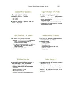
Transcription of Motor Calculations
1 Motor Calculations Calculating Mechanical power Requirements Torque - Speed Curves Numerical Calculation Sample Calculation Thermal Calculations Calculating Mechanical power Requirements Physically, power is defined as the rate of doing work. For linear motion, power is the product of force multiplied by the distance per unit time. In the case of rotational motion, the analogous calculation for power is the product of torque multiplied by the rotational distance per unit time. =MProt Where: Prot = rotational mechanical power M = torque = angular velocity The most commonly used unit for angular velocity is rev/min (RPM).
2 In calculating rotational power , it is necessary to convert the velocity to units of rad/sec. This is accomplished by simply multiplying the velocity in RPM by the constant (2 x ) /60: =602sec/ rpmrad It is important to consider the units involved when making the power calculation. A reference that provides conversion tables is very helpful for this purpose. Such a reference is used to convert the torque-speed product to units of power (Watts). Conversion factors for commonly used torque and speed units are given in the following table. These factors include the conversion from RPM to rad/sec where applicable.
3 Torque Units Speed Units Conversion Factor oz-in RPM oz-in rad/sec in-lb RPM in-lb rad/sec ft-lb RPM ft-lb rad/sec N-m RPM N-m rad/sec For example, assume that it is necessary to determine the power required to drive a torque load of 3 oz-in at a speed of 500 RPM. The product of the torque, speed, and the appropriate conversion factor from the table is: Calculation of power requirements is often used as a preliminary step in Motor or gearmotor selection. If the mechanical power required for a given application is known, then the maximum or continuous power ratings for various motors can be examined to determine which motors are possible candidates for use in the application.
4 Torque - Speed Curves One commonly used method of displaying Motor characteristics graphically is the use of torque - speed curves. While the use of torque - speed curves is much more common in technical literature for larger DC machines than it is for small, ironless core devices, the technique is applicable in either case. Torque - speed curves are generated by plotting Motor speed, armature current, mechanical output power , and efficiency as functions of the Motor torque. The following discussion will describe the construction of a set of torque - speed curves for a typical coreless DC Motor from a series of raw data measurements.
5 Motor 1624E009S is used as an example. Assume that we have a small Motor that we know has a nominal voltage of 9 volts. With a few fundamental pieces of laboratory equipment, the torque - speed curves for the Motor can be generated: Step One (measure basic parameters): Using a voltage supply set to 9 volts, run the Motor unloaded and measure the rotational speed using a non-contacting tachometer (strobe, for instance). Measure the Motor current under this no-load condition. A current probe is ideal for this measurement since it does not add resistance in series with the operating Motor .
6 Using an adjustable torque load such as a small particle brake coupled to the Motor shaft, increase the torque load to the Motor just to the point where stall occurs. At stall, measure the torque from the brake and the Motor current. For the sake of this discussion, assume that the coupling adds no load to the Motor and that the load from the brake does not include unknown frictional components. It is also useful at this point to measure the terminal resistance of the Motor . Measure the resistance by contacting the Motor terminals. Then spin the Motor shaft and take another measurement.
7 The measurements should be very close in value. Continue to spin the shaft and take at least three measurements. This will ensure that the measurements were not taken at a point of minimum contact on the commutator. Now we have measured the: n0= no-load speed I0= no-load current MH= stall torque R= terminal resistance Step Two (plot current vs. torque and speed vs torque) Prepare a graph with Motor torque on the horizontal axis, Motor speed on the left vertical axis, and Motor current on the right vertical axis. Scale the axes based on the measurements in step 1. Draw a straight line from the left origin of the graph (zero torque and zero current) to the stall current on the right vertical axis (stall torque and stall current).
8 This line represents a plot of the Motor current as a function of the Motor torque. The slope of this line is the proportionality constant for the relationship between Motor current and Motor torque (in units of current per unit torque). The reciprocal of this slope is the torque constant of the Motor (in units of torque per unit current). For the resulting curves see Graph 1. Using the relationships between Motor constants discussed earlier, calculate the velocity constant of the Motor from the torque constant obtained above. By multiplying the velocity constant by the nominal Motor voltage, obtain the theoretical no-load speed of the Motor (zero torque and no-load speed) and plot it on the left vertical axis.
9 Draw a straight line between this point and the stall torque and zero speed point on the graph. The slope of this line is the proportionality constant for the relationship between Motor speed and Motor torque (in units of speed per unit torque). The slope of the line is negative, indicating that Motor speed decreases with increasing torque. This value is sometimes called the regulation constant of the Motor . For the resulting curves see Graph 1. For the purpose of this discussion, it will be assumed that the Motor has no internal friction. In practice, the Motor friction torque is determined using the torque constant of the Motor and the measured no-load current.
10 The torque vs speed line and the torque vs current line are then started not at the left vertical axis but at an offset on the horizontal axis equal to the calculated friction torque. Step Three (plot power vs torque and efficiency vs torque) In most cases, two additional vertical axes are added for plotting power and efficiency as functions of torque. A second left vertical axis is usually used for efficiency and a second right vertical axis is used for power . For the sake of simplifying this discussion, efficiency vs. torque and power vs. torque will be plotted on a second graph separate from the speed vs.