Transcription of Motor Protection - Electrical Sector
1 133 2005 Cooper BussmannFor Summary of Suggestions to Protect Three-Phase Motors AgainstSingle-Phasing see the end of this section, page , the causes of Motor failure can be attributed to:Overloads30%Contaminants19%Single-pha sing14%Bearing failure13%Old age10%Rotor failure5%Miscellaneous9%100%From the above data, it can be seen that 44% of Motor failure problems arerelated to a Motor to reach and operate at a temperature 10 C above its maximum temperature rating will reduce the Motor s expected life by 50%.Operating at 10 C above this, the Motor s life will be reduced again by 50%.This reduction of the expected life of the Motor repeats itself for every 10 is sometimes referred to as the half life there is no industry standard that defines the life of an electric Motor ,it is generally considered to be 20 term, temperature rise , means that the heat produced in the Motor windings (copper losses), friction of the bearings, rotor and stator losses (corelosses), will continue to increase until the heat dissipation equals the heatbeing generated.
2 For example, a continuous duty, 40 C rise Motor will stabilize its temperature at 40 C above ambient (surrounding) motors are designed so the temperature rise produced within themotor, when delivering its rated horsepower, and added to the industry standard 40 C ambient temperature rating, will not exceed the safe windinginsulation temperature term, Service Factor for an electric Motor , is defined as: a multiplierwhich, when applied to the rated horsepower, indicates a permissible horsepower loading which may be carried under the conditions specified forthe Service Factor of the Motor . Conditions include such things as operating the Motor at rated voltage andrated : A 10Hp Motor with a SF can produce 10Hp of work withoutexceeding its temperature rise requirements. A 10Hp Motor with a SF canproduce of work without exceeding its temperature rise , with the resulting overcurrents, if allowed to continue, will causeheat build-up within the Motor .
3 The outcome will be the eventual early failureof the Motor s insulation. As stated previously for all practical purposes, insulation life is cut in half for every 10 C increase over the Motor s rated UnbalanceWhen the voltage between all three phases is equal (balanced), current valueswill be the same in each phase NEMA standard for electric motors and generators recommends that themaximum voltage unbalance be limited to 1%.When the voltages between the three phases (AB, BC, CA) are not equal(unbalanced), the current increases dramatically in the Motor windings, and ifallowed to continue, the Motor will be is possible, to a limited extent, to operate a Motor when the voltage betweenphases is unbalanced. To do this, the load must be UnbalanceDerate Motor to Thesein PercentPercentages of the Motor s Rating*1%98%2%95%3%88%4%82%5%75%*This is a general rule of thumb , for specific motors consult the Motor Causes of Unbalanced Voltage Conditions Unequal single-phase loads.
4 This is why many consulting engineersspecify that loading of panelboards be balanced to 10% between allthree phases. Open delta connections. Transformer connections open - causing a single-phase condition. Tap settings on transformer(s) not proper. Transformer impedances (Z) of single-phase transformers connected into a bank not the same. Power factor correction capacitors not the same, .or off the LifeThe effect of voltage unbalance on the insulation life of a typical T-frame motorhaving Class B insulation, running in a 40 C ambient, loaded to 100%, is asfollows:Insulation LifeVoltageService FactorService that motors with a service factor of do not have as much heat withstand capability as do motors having a service factor of , larger U-frame motors, because of their ability to dissipate heat, couldwithstand overload conditions for longer periods of time than the newer.
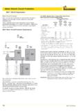
5 Smaller T-frame ClassesThe following shows the maximum operating temperatures for different classesof A Insulation105 CClass B Insulation130 CClass F Insulation155 CClass H Insulation180 CMotor ProtectionVoltage Unbalance & Single-Phasing134 2005 Cooper BussmannHow to Calculate Voltage Unbalance and The Expected Rise in HeatMotor ProtectionVoltage Unbalance & Single-PhasingPhase APhase BPhase C248 Volts230 Volts236 Volts3 MOTORM otor Overload DevicesThree-PhaseSourceOpenTwo Motor overload protective devices cannot assure protectionagainst the effects of PRIMARY single-phasing. The middle linecurrent increase to 230% is not of Normal Current 115% of Normal Current 115% of Normal Current 3 MOTOR3 MOTORNEC REQUIREMENTT hree-phase motors r equire three Motor overload protective devicesThree-Phase SourceStep 1: Add together the three voltage readings:248 + 236 + 230 = 714 VStep 2: Find the average = 238V/3 Step 3: Subtract the average voltage from one of the voltages that will indicate the greatest voltage difference.
6 In this example:248 238 = 10 VStep 4: 100 x greatest voltage difference average voltage = 100 x 10 = voltage unbalance 238 Step 5: Find the expected temperature rise in the phase winding with the highest current by taking 2 x (percent voltage unbalance)2In the above example:2 x ( )2 = percent temperature , for a Motor rated with a 60 C rise, the unbalanced voltage condition in the above example will result in a temperature rise in the phasewinding with the highest current of:60 C x = CThe National Electrical Code The National Electrical Code , in Table , requires three over-load protective devices, one in each phase, for the Protection of all to the 1971 National Electrical Code , three-phase motors were consid-ered to be protected from overload (overcurrent) by two overload protectivedevices.
7 These devices could be in the form of properly sized time-delay, dual-element fuses, or overload heaters and relays (melting alloy type, bi-metallictype, magnetic type, and solid-state type.)Three-phase motors protected by two overload protective devices are notassured Protection against the effect of single-phasing. For example, when theelectrical system is WYE/DELTA or DELTA/WYE connected, all three phaseson the secondary side of the transformer bank will continue to carry currentwhen a single-phasing caused by an open phase on the primary side of thetransformer bank occurs. As will be seen later, single-phasing can be considered to be the worst caseof unbalanced voltage of a WYE/DELTA transformation with one primary phase open. The Motor isprotected by two overload devices. Note that one phase to the Motor is carrying twotimes that of the other two phases.
8 Without an overload device in the phase that iscarrying two times the current in the other two phases, the Motor will burn National Electrical Code , Section requires that when fuses areused for Motor overload Protection , a fuse shall be inserted in each thermal overload devices, heaters, etc. are used for Motor overloadprotection, Table requires one be inserted in each phase. With theserequirements, the number of single-phasing Motor burnouts are greatlyreduced, and are no longer a serious hazard to Motor installations. The following figure shows three overload protective devices protecting the three-phase 1971, The National Electrical Code has required three overload protectivedevices for the Protection of three-phase motors, one in each Branch Circuit, Short Circuit and Ground Fault ProtectionWhen sized according to NEC , a 3-pole common trip circuit breakeror MCP can not protect against single-phasing should be emphasized, the causes of single-phasing cannot be , motors can be protected from the damaging effects of single-phasing through the use of proper overcurrent , time-delay fuses can be sized at or close to the Motor s nameplate full-load amp rating without opening on normal Motor start-up.
9 Thiswould require sizing the fuses at 100-125% of the motors full-load current rating. Since all motors are not necessarily fully loaded, it is recommendedthat the actual current draw of the Motor be used instead of the nameplate rating. This is possible for Motor s that have a fixed load, but not recommended where the Motor load varies.*Diagram showing two overload devices protecting a three-phase Motor . This wasacceptable by the National Electrical Code prior to Motor overload protective devices provide adequate Protection againstbalanced voltage overload conditions where the voltage between phases isequal. When a balanced voltage over-load persists, the protective devicesusually open simultaneously. In some cases, one device opens, and shortlythereafter, the second device opens. In either case, three-phase motors areprotected against balanced voltage overload 2005 Cooper BussmannThus, when single-phasing occurs, Fusetron FRS-R and FRN-R and Low-Peak LPS-RK_SP and LPN-RK_SP dual-element, time-delay fuses will sensethe overcurrent situation and respond accordingly to take the Motor off Motor branch-circuit Protection only, the following sizing guidelines of the National Electrical Code are Dual-element, time-175%225%delay fuses Non-time-delay fuses300%400%and all Class CC fuses Inverse-time circuit250%400% for motorsbreaker100 ampsor for motorsmore than100 amps.
10 Instantaneous only trip**800% 1300% circuit breakers(sometimes referred to as MCPs. These are Motor circuit protectors,not Motor protectors.) See NEC for specifics and exceptions. 1100% for other than design B energy efficient motors. 1700% for design B motors.*When sizing to the actual running current of the Motor is not practical, aneconomic analysis can determine if the addition of one of the electronic blackboxes is financially justified. These electronic black boxes can sense voltageand current unbalance, phase reversal, single-phasing, etc.**Instantaneous only trip breakers are permitted to have time-delay. This couldresult in more damaging let-through current during short : When sized according to table , none of these overcurrentdevices can provide single-phasing term single-phasing, means one of the phases is open.