Transcription of MPFI FUEL INJECTION SYSTEM
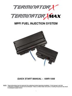
1 1 MPFI fuel INJECTION SYSTEM PART NUMBERS 550-903 thru 905, 550-916 thru 918 & 550-926 thru 931 INSTALLATION & TUNING MANUAL 199R11760 2 NOTE: These instructions must be read and fully understood before beginning installation. If this manual is not fully understood, installation should not be attempted. Failure to follow these instructions, including the pictures may result in subsequent SYSTEM failure. TABLE OF CONTENTS: INTRODUCTION .. 3 WARNINGS, NOTES, AND NOTICES .. 3 PARTS IDENTIFICATION .. 4 ADDITIONAL ITEMS REQUIRED FOR INSTALLATION .. 4 TOOLS REQUIRED FOR INSTALLATION .. 5 REMOVAL OF EXISTING COMPONENTS .. 5 terminator X MPFI SYSTEM 5 fuel Pump, fuel Line, and Filter 5 Oxygen Sensor Installation.
2 5 Oxygen Sensor Mounting Procedure .. 6 ECU Mounting .. 6 WIRING .. 6 Important Wiring Do s and Don ts .. 6 WIRING HARNESS INSTALLATION .. 7 Main Power/Battery Connection .. 7 PRIMARY HARNESS INSTALLATION AND SENSOR CONNECTIONS .. 7 ECU Connectors .. 8 Harness Routing .. 8 Sensor Connections & Outputs .. 8 Oil Pressure Sensor .. 8 Coolant Temperature Sensor (CTS) .. 9 Wide Band Oxygen Sensor (WB02) need text about adapter harness need pics .. 9 fuel Pressure ( fuel ) .. 9 Manifold Air Temperature (MAT) .. 9 Cam Sensor .. 10 Crank Sensor .. 10 Knock Sensors .. 10 Manifold Absolute Pressure sensor (MAP).. 10 Throttle Position Sensor (TPS) .. 11 Idle Air Control (IAC).
3 11 fuel Injectors .. 11 Ignition Coils .. 12 Coil Ground Wires .. 12 Handheld Connections - (CAN1) .. 12 LOOSE WIRES .. 13 ADDITIONAL OUTPUTS .. 13 TRANSMISSION HARNESS .. 14 Transmission Wiring .. 14 DRIVE-BY-WIRE 15 Overview .. 15 Warnings! .. 15 Installation .. 15 SYSTEM Safeties .. 16 Throttle Body Limp Home Position .. 16 Drive-By-Wire DO S and DON TS .. 16 Wiring .. 16 PREVIOUS INSTALLATION REQUIRED .. 17 terminator INSTRUCTIONS AND TUNING .. 17 INITIAL POWER-UP .. 17 HANDHELD NAVIGATION & USE .. 17 Making Adjustments .. 17 HOME SCREEN .. 18 CALIBRATION WIZARD .. 19 TPS AUTOSET .. 23 SENSOR VERIFICATION .. 24 STARTUP .. 24 AFTER-STARTUP .. 25 IDLE SETTING/CABLE OPERATED THROTTLE PLATE SETTING.
4 25 SELF-TUNING .. 26 3 INTRODUCTION Holley Performance Products has written this manual for the installation of the LS terminator X MPFI fuel INJECTION SYSTEM . This manual contains the information necessary for the installation of the hardware contained in this kit, which includes the ECU, wiring, and touch screen. It also contains basic tuning information. This instruction sheet does not include installation instructions for the fuel SYSTEM (pump, filters, regulators and lines). Please read all the WARNINGS and NOTES, as they contain valuable information that can save you time and money. It is our intent to provide the best possible products for our customer; products that perform properly and satisfy your expectations.
5 Should you need information or parts assistance, please contact our technical service department at 1-866-464-6553, Monday through Friday, 8 to 5 Central Time. By using this number, you may obtain any information and/or parts assistance that you may require. Please have the part number of the product you purchased when you call. WARNINGS, NOTES, AND NOTICES NOTE: This SYSTEM does not contain fuel SYSTEM components that are required including the fuel pump, fuel filters, fuel pressure regulator, and lines. Holley offers complete kits can be purchased separately (526-1, 526-2, 526-3, & 526-4). NOTE: This SYSTEM is designed for stock and mild cam, naturally aspirated LS engines. WARNING! The LS terminator X MPFI systems consist of a number of sophisticated components.
6 Failure of any one component does not constitute, nor does it justify, warranty of the complete SYSTEM . Individual service items are available for replacement of components. If assistance is required or if you need further warranty clarification, you can call Holley Technical Service at the number shown above. WARNING! To preserve warranty, these instructions must be read and followed thoroughly and completely before and during installation. It is important that you become familiar with the parts and the installation of the LS terminator X MPFI SYSTEM before you begin. Failure to read and understand these instructions could result in damage to LS terminator X MPFI components that are not covered by the warranty and could result in serious personal injury and property damage.
7 WARNING! The oxygen sensor in this kit is recommended for use with ONLY unleaded fuel . Use of leaded fuels will degrade the oxygen sensor and will result in incorrect exhaust gas oxygen readings and improper fuel delivery. Failure to follow these directions does not constitute the right to a warranty claim. WARNING! Failure to follow all of the above will result in an improper installation, which may lead to personal injury, including death, and/or property damage. Improper installation and/or use of this or any Holley product will void all warranties. WARNING! Use of some RTV silicone sealers will destroy the oxygen sensor used with this product. Ensure the RTV silicone sealant you use is compatible with oxygen sensor vehicles.
8 This information should be found on the RTV package. WARNING! For the safety and protection of you and others, only a trained mechanic having adequate fuel SYSTEM experience must perform the installation, adjustment, and repair. It is particularly important to remember one of the very basic principles of safety: fuel vapors are heavier than air and tend to collect in low places where an explosive fuel /air mixture may be ignited by any spark or flame resulting in property damage, personal injury, and/or death. Extreme caution must be exercised to prevent spillage and thus eliminate the formation of such fuel vapors. WARNING! This type of work MUST be performed in a well-ventilated area. Do not smoke or have an open flame present near gasoline vapors or an explosion may result.
9 4 PARTS IDENTIFICATION ITEM DESCRIPTION QTY SERVICE PART 1A terminator X ECU (Kits 550-903, 904 & 905) 1 1B terminator X MAX ECU (Kits 550-916 thru 918, 550-926 thru 931) 1 2 terminator X Hand-Held Controller 1 553-201 3 Main Power Harness 1 558-308 4A Main Engine Harness (LS1 - 24x) 1 558-102 4B Main Engine Harness (LS2/3/7 - 58x) 1 558-103 5A Injector Harness (EV1) 1 558-200 5B Injector Harness (EV6) 1 550-201 5C Injector Harness (Truck) 1 558-214 6 Input/Output Harness 1 558-462 7A Drive-By-Wire Harness 1 558-406 7B Drive-By-Wire Harness Early Truck 1 558-429 8 4L60E/4L80E Transmission Harness 1 558-405 9 Wideband O2 Adapter Harness 1 558-463 10 Quick Turn MAP Sensor Adapters (1/8 , 3/16 , 1/4 ) 1 543-121 11 Oxygen Sensor 1 554-155 12 Oxygen Sensor Weld Ring 1 534-49 Service Parts: 13 40 AMP Relay 1 534-26 Optional Parts.
10 14 100 PS fuel Pressure or Oil Pressure Sender 1 554-102 15 LS MAP Sensor Adapter Harness 1 558-116 16 USB to CAN Tuning Cable 1 558-443 Item 1A Item 1B Item 2 Item 3 Item 4A Item 4B Item 5A Item 5B Item 5C Item 6 Item 7A Item 7B Item 8 Item 9 Item 10 Item 11 Item 12 Item 13 Item 14 ADDITIONAL ITEMS REQUIRED FOR INSTALLATION fuel SYSTEM Return fuel Lines A 0-100 psi fuel gauge or pressure transducer is recommended to check for proper fuel pressure.