Transcription of MPFI FUEL INJECTION SYSTEM
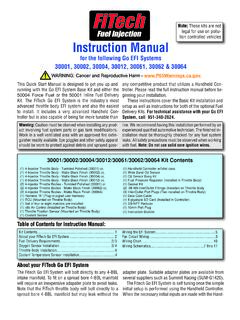
1 1 MPFI fuel INJECTION SYSTEM QUICK START MANUAL 199R11956 NOTE: These instructions must be read and fully understood before beginning installation. If this manual is not fully understood, installation should not be attempted. Failure to follow these instructions, including the pictures may result in subsequent SYSTEM failure. 2 TABLE OF CONTENTS: INTRODUCTION .. 3 WARNINGS, NOTES, AND NOTICES .. 3 ADDITIONAL ITEMS REQUIRED FOR INSTALLATION .. 3 TOOLS REQUIRED FOR INSTALLATION .. 4 REMOVAL OF EXISTING COMPONENTS .. 4 terminator X MPFI SYSTEM 4 fuel Pump, fuel Line, and Filter 4 Oxygen Sensor Installation .. 4 Oxygen Sensor Mounting Procedure .. 5 ECU Mounting .. 5 WIRING .. 5 Important Wiring Do s and Don ts .. 5 WIRING HARNESS INSTALLATION .. 6 Main Power/Battery Connection .. 6 PRIMARY HARNESS INSTALLATION AND SENSOR CONNECTIONS .. 6 ECU Connectors .. 7 Harness Routing .. 7 Sensor Connections & Outputs.
2 7 Oil Pressure Sensor .. 8 Coolant Temperature Sensor (CTS) .. 8 Wide Band Oxygen Sensor (WBO2) .. 8 fuel Pressure ( fuel ) .. 8 Manifold Air Temperature (MAT) .. 9 Ignition / Crank and Cam Sensors .. 9 Knock Sensors .. 10 Manifold Absolute Pressure sensor (MAP).. 10 Throttle Position Sensor (TPS) .. 11 Idle Air Control (IAC) .. 11 fuel Injectors .. 11 Ignition Coils .. 12 Coil Ground Wires .. 12 Handheld Connections - (CAN1) .. 12 LOOSE WIRES .. 13 ADDITIONAL INPUTS & OUTPUTS .. 13 TRANSMISSION HARNESS .. 14 GM Transmission Wiring .. 14 Ford Transmission Wiring .. 16 DRIVE-BY-WIRE 17 Overview .. 17 Warnings! .. 17 Installation .. 17 SYSTEM Safeties .. 17 Throttle Body Limp Home Position .. 18 Drive-By-Wire DO S and DON TS .. 18 GM DBW Wiring .. 18 Ford DBW Wiring .. 19 Chrysler DBW Wiring .. 19 FINAL ECU CONNECTION .. 19 terminator X INSTRUCTIONS AND TUNING .. 19 INITIAL POWER-UP .. 20 HANDHELD NAVIGATION & USE.
3 20 Making Adjustments .. 20 HOME SCREEN .. 21 CALIBRATION WIZARD .. 21 TPS AUTOSET .. 27 SENSOR VERIFICATION .. 28 STARTUP .. 28 AFTER-STARTUP .. 28 IDLE SETTING/CABLE OPERATED THROTTLE PLATE SETTING .. 29 SELF-TUNING .. 29 IGNITION WIRING DIAGRAMS .. 30 DIAGNOSTIC LED S .. 37 3 INTRODUCTION Holley Performance Products has written this manual for the installation of the terminator X MPFI fuel INJECTION SYSTEM . This manual contains the information necessary for the installation of the hardware contained in this kit, which includes the ECU, wiring, and touch screen. It also contains basic tuning information. This instruction sheet does not include installation instructions for the fuel SYSTEM (pump, filters, regulators and lines). Please read all the WARNINGS and NOTES, as they contain valuable information that can save you time and money. It is our intent to provide the best possible products for our customer; products that perform properly and satisfy your expectations.
4 Should you need information or parts assistance, please contact our technical service department at 1-866-464-6553, Monday through Friday, 8 to 5 Central Time. By using this number, you may obtain any information and/or parts assistance that you may require. Please have the part number of the product you purchased when you call. WARNINGS, NOTES, AND NOTICES NOTE: This SYSTEM does not contain fuel SYSTEM components that are required including the fuel pump, fuel filters, fuel pressure regulator, and lines. Holley offers complete kits can be purchased separately (526-1, 526-2, 526-3, & 526-4). WARNING! The terminator X MPFI systems consist of a number of sophisticated components. Failure of any one component does not constitute, nor does it justify, warranty of the complete SYSTEM . Individual service items are available for replacement of components. If assistance is required or if you need further warranty clarification, you can call Holley Technical Service at the number shown above.
5 WARNING! To preserve warranty, these instructions must be read and followed thoroughly and completely before and during installation. It is important that you become familiar with the parts and the installation of the terminator X MPFI SYSTEM before you begin. Failure to read and understand these instructions could result in damage to terminator X MPFI components that are not covered by the warranty and could result in serious personal injury and property damage. WARNING! The oxygen sensor in this kit is recommended for use with ONLY unleaded fuel . Use of leaded fuels will degrade the oxygen sensor and will result in incorrect exhaust gas oxygen readings and improper fuel delivery. Failure to follow these directions does not constitute the right to a warranty claim. WARNING! Failure to follow all of the above will result in an improper installation, which may lead to personal injury, including death, and/or property damage. Improper installation and/or use of this or any Holley product will void all warranties.
6 WARNING! Use of some RTV silicone sealers will destroy the oxygen sensor used with this product. Ensure the RTV silicone sealant you use is compatible with oxygen sensor vehicles. This information should be found on the RTV package. WARNING! For the safety and protection of you and others, only a trained mechanic having adequate fuel SYSTEM experience must perform the installation, adjustment, and repair. It is particularly important to remember one of the very basic principles of safety: fuel vapors are heavier than air and tend to collect in low places where an explosive fuel /air mixture may be ignited by any spark or flame resulting in property damage, personal injury, and/or death. Extreme caution must be exercised to prevent spillage and thus eliminate the formation of such fuel vapors. WARNING! This type of work MUST be performed in a well-ventilated area. Do not smoke or have an open flame present near gasoline vapors or an explosion may result. ADDITIONAL ITEMS REQUIRED FOR INSTALLATION fuel SYSTEM Return fuel Lines A 0-100 psi fuel gauge or pressure transducer is recommended to check for proper fuel pressure.
7 PN 554-102 is a 0-100 PSI pressure sensor that can be purchased as well that will plug into the terminator X harness to check and monitor fuel pressure. It requires a 1/8 NPT port for installation (Holley fuel pressure regulators have a 1/8 NPT port). 4 TOOLS REQUIRED FOR INSTALLATION Standard wrench set Small blade screwdriver Allen wrench set Medium blade screwdriver #2 Phillips screwdriver Digital volt meter Drill and assorted bit sizes Hole saw (2 ) (depending on ECU location) Terminal crimping tool Factory Service Manual for your vehicle O2 Bung Installation (drilling, welding) An assistant is necessary for some installation and adjustment procedures and should be present for safety reasons. REMOVAL OF EXISTING COMPONENTS 1. Disconnect the battery. 2. If applicable, remove the existing OEM main wiring harness and injector harness. Consult the factory service manual for details on how to properly remove the harness.
8 terminator X MPFI SYSTEM INSTALLATION fuel Pump, fuel Line, and Filter Installation A complete high pressure EFI fuel SYSTEM must be installed for the terminator X . The pump should be capable of supplying a minimum of 255 liters/hour or 400 of fuel at 43 psi. If using an in-line fuel pump, there should be a coarse pre-filter before the pump. All systems should contain a 10 micron post filter after the fuel pump. An EFI fuel pressure regulator is required. It should be installed after the fuel rail. See Figure 1 below for proper fuel SYSTEM plumbing. Holley offers multiple fuel SYSTEM kits. These kits contain all components except the return line. They include detailed instructions (downloadable at ). Examples of these kits are: 526-1 Braided Stainless Lines, Billet Pump, Regulator, and Filters 526-2 Pro-Lite 350 Hose, Billet Pump, Regulator, and Filters 526-3 Super Stock Hose, Billet Regulator, 12-920 fuel Pump, and Filter 526-4 Super Stock Hose, Billet Regulator, 12-920 Pump, and Metal Filters Figure 1 Oxygen Sensor Installation The oxygen sensor should be mounted at a point where it can read a good average of all the cylinders on one bank.
9 This would be slightly after all the cylinders merge. Do NOT mount the sensor far back in the exhaust as this will negatively impact closed loop operation response. If you have long tube headers, mount the sensor approximately 1-10 after the collector. You must have no less than 18 24 of exhaust pipe after the sensor. terminator X EFI systems come with a Bosch LSU wideband oxygen sensor. Make sure your sensor looks like Figure 2. Figure 2 fuel Rail 5 Oxygen Sensor Mounting Procedure NOTE: Never run the engine with the oxygen sensor installed if it is not plugged in and powered by the ECU, or it will be damaged. If you need to plug the hole temporarily, use an O2 sensor plug or a spark plug with an 18mm thread. NOTE: Someone with experience in welding exhaust systems should install the oxygen sensor boss. Any competent exhaust shop will be able to perform this task at a minimum cost. (Note: If you weld on the car, make sure all wiring to the ECU is disconnected, and its best to remove the ECU from the vehicle when welding).
10 WARNING! Use of leaded fuel will degrade an oxygen sensor. Prolonged use is not recommended unless periodic replacement is performed. WARNING! Use of some RTV silicone sealers will destroy the oxygen sensor used with this product. Ensure the RTV silicone sealant you use is compatible with oxygen sensor vehicles. This information should be found on the RTV package. 1. Locate a position for the oxygen sensor as close to the engine as possible. If your vehicle has catalytic converters, the oxygen sensor MUST be located between the engine and the catalytic converters. Figure 3 NOTE: The oxygen sensor should be mounted in such a way that the condensation in the exhaust tubing will not enter the sensor. Mount the O2 sensor in the upper half of the exhaust tubing, with the angle x , shown above, being greater than 10 . Figure 3 indicates that the sensor can be mounted on either side of the exhaust tubing. 2. Drill a 7/8 hole in the location picked for the sensor. Weld the threaded boss into the 7/8 hole.