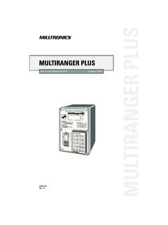
Transcription of multiranger - PRTS
1 Instruction Manual April 2005100/200multiranger Siemens Milltronics Process Instruments Inc. 2005 Safety Guidelines: Warning notices must be observed to ensure personal safety as well as that of others, and to protect the product and the connected equipment. These warning notices are accompanied by a clarification of the level of caution to be observed. Qualified Personnel: This device/system may only be set up and operated in conjunction with this manual. Qualified personnel are only authorized to install and operate this equipment in accordance with established safety practices and standards. Unit Repair and Excluded Liability: The user is responsible for all changes and repairs made to the device by the user or the user s agent. All new components are to be provided by Siemens Milltronics Process Instruments Inc.
2 Restrict repair to faulty components only. Do not reuse faulty components. Warning: This product can only function properly and safely if it is correctly transported, stored, installed, set up, operated, and maintained. Note: Always use product in accordance with specifications. Copyright Siemens Milltronics Process Instruments Inc. 2005. All Rights Reserved Disclaimer of Liability This document is available in bound version and in electronic version. We encourage users to purchase authorized bound manuals, or to view electronic versions as designed and authored by Siemens Milltronics Process Instruments Inc. Siemens Milltronics Process Instruments Inc. will not be responsible for the contents of partial or whole reproductions of either bound or electronic versions. While we have verified the contents of this manual for agreement with the instrumentation described, variations remain possible.
3 Thus we cannot guarantee full agreement. The contents of this manual are regularly reviewed and corrections are included in subsequent editions. We welcome all suggestions for improvement. Technical data subject to change. MILLTRONICS is a registered trademark of Siemens Milltronics Process Instruments Inc. Contact SMPI Technical Publications at the following address: Technical Publications Siemens Milltronics Process Instruments Inc. 1954 Technology Drive, Box 4225 Peterborough, Ontario, Canada, K9J 7B1 Email: For a selection of Siemens Milltronics level measurement manuals, go to: www. Under Process Instrumentation, select Level Measurement and then go to the manual archive listed under the product family. For a selection of Siemens Milltronics weighing manuals, go to: www. Under Weighing Technology, select Continuous Weighing Systems and then go to the manual archive listed under the product family.
4 ImmmmmTable of ContentsTa b l e o f C o n t e n t sThe multiranger 100 and 200 ..1 multiranger 100 ..1 multiranger 200 ..1 The Manual ..1 Manual Symbols ..2 Configuration Examples ..2 Specifications ..3 Installation ..8 Mounting ..8 Mounting Locations ..8 Mounting Instructions ..9 Wall Mount .. 9 Cable routed through a conduit: .. 10 Panel Mount .. 11 Mounting the Enclosure .. 12 multiranger Board ..13 Installing the Battery ..13 Installing SmartLinx Card ..14 Optional Equipment ..14 Wiring ..15 Terminal Board ..16 Cables ..16 Transducers ..17 Relays ..17 Temperature Sensor ..18mA Input [MR 200 only] ..18mA Output ..18 Level System Synchronization ..19 Power ..19 Digital Communications ..20RS-232 Serial Connection ..20RS-485 Serial Connection ..20 Discrete 20 Operating the multiranger .
5 21 RUN Mode ..21 Readings in RUN Mode ..22 Status Parameters ..23 Controlling the Display ..24 Adjusting the primary reading for four-digit LCD readout:.. 24 Auxiliary Reading ..24 Multiple Readings [MR 200 only] ..25 PROGRAM Mode ..26 iimmmmmTa b l e o f C o n t e n t sStarting PROGRAM Mode ..26 Hand Programmer ..26 Programmer Keys ..27 Dolphin Plus ..28 Dolphin Plus Toolbar Buttons ..29 SIMATIC Process Device Manager (PDM) ..30 Device Description ..30 Activating the multiranger ..31 Changing Parameters ..31 Security ..32 Using Units or Percent (%) ..32 Parameters Types ..32 Parameter Reset ..33 Display Readout ..33 Changing Parameters(Dolphin Plus) ..34 Parameter Indexing ..35 Primary and Secondary Indexes ..36 Primary Index .. 36 Secondary 36 Starting Measurement ..37 Single Point Models.
6 37 Average or Differential [MR 200 only] .. 38 Dual Point Models ..38 Average or Differential [MR 200 only] .. 39 Measurement Conditions ..39 Response Rate .. 39 Dimensions [MR 200 only].. 39 Relays ..40 General Introduction ..40 Relay Function ..40 Alarm .. 41 Relay Status Non Run Modes .. 42 Relay States ..42 Relay Related Parameters ..42 Relay Wiring Test .. 43 Relay Activation ..43 Relay Failsafe ..44 Preset Applications ..45 Backup Level Override ..46 Backup Level Override Parameters ..46 Discrete Inputs ..47 Wiring the Discrete Inputs ..47 Programming the Discrete Input Logic ..47 iiimmmmmTable of ContentsmA I/O ..48mA Input [MR 200] ..48mA Output ..48 Volume [MR 200] ..50 Readings ..50 Tank Shape and Dimensions ..50 Characterization Chart [MR 200] ..51 Example Chart ..51 multiranger 200 only.
7 52 Alarms ..53 Level ..53 Setting Simple Level Alarms ..54 Rate [MR 200] ..54In Bounds/ Out of Bounds Range [MR 200] ..55 Cable Fault ..55 Temperature [MR 200] ..55 Loss of Echo (LOE) ..56 Pump Control ..57 Setting a Pump Down Group ..57 Setting a Pump Up (Reservoir) Group ..58 Other Pump Control Algorithms ..60 Set Relays to ALTERNATE DUTY BACKUP [MR 200] ..60 Set Relays to FIXED DUTY ASSIST ..60 Set Relays to FIXED DUTY BACKUP [MR 200] ..61 Set Relays to ALTERNATE DUTY SERVICE [MR 200] ..61 Set Relays to FIRST IN FIRST OUT (FIFO) ASSIST [MR 200] ..62 Optional Pump Controls ..62 Starting Pumps by Rate of Level Change [MR 200] ..62 Rotating Pumps by Service Ratio [MR 200] ..63 Totalizing Pumped Volume [MR 200] ..64 Setting Independent Failsafe Controls ..64 Setting a Pump to Run On [MR 200].
8 65 Setting the Pump Start Delays [MR 200] ..65 Reducing Wall Cling [MR 200] ..65 Grouping Pumps [MR 200] ..66 Setting a Flush Valve [MR 200] ..66 Relay Controlled by Communications ..67 Tracking Pump Usage ..67 Rake (Screen) Control [MR 200] ..68 Setting a Rake Control ..68 ivmmmmmTa b l e o f C o n t e n t sSetting the Common Parameters ..69 Set Relay 1 (Operate Rake) ..69 Set Relays 2 to 4 (Level Alarms) ..69 External Totalizers and Flow Samplers [MR 200] ..70 Relay Contacts ..70 Totalizer ..70 Flow Sampler ..71 Based on Volume and Time ..71 Open Channel Monitoring (OCM) [MR 200] ..72 Common Parameters ..72 Setting Zero Head ..73 Setting Totalized Volume ..74 Applications Supported by multiranger 200 ..74BS-3680 / ISO 1438/1 Thin plate V notch weir .. 74BS-3680 / ISO 4359 Rectangular Flume.
9 75 Palmer Bowlus Flume .. 76H Flume .. 77 PMDs with Exponential Flow to Head Function ..78 Applicable Weir Profiles ..78 Non-Applicable Weir Profiles ..79 Parshall Flume ..79 Leopold Lagco Flume ..80 Cut Throat Flume ..81 Universal Calculation Support ..82 Typical Flow Characterization ..82 Example Flumes ..83 Example Weirs ..83 Testing the Configuration ..85 Simulation ..85 Simulating a Single Measurement ..85 Simulating a Level Cycle ..85 Checking Volume Characterization [MR 200] ..86 Checking OCM Flow Characterization [MR 200] ..86I/O Checkout ..87 Application Test ..87 multiranger Communications ..89 multiranger Communication Systems ..89 Optional SmartLinx Cards ..89 Communication Systems ..90 Communication Ports ..90 Modbus ..90 SmartLinx ..91 Dolphin Plus ..91 vmmmmmTable of ContentsCommunications Installation.
10 92 Wiring Guidelines ..92 Ports 1 and 2 ..92 Ports 1 and 2: RS-232 RJ-11 Jack and RS-485 Locations ..92 Port 1: RS-232 RJ-11 Jack ..93 Port 2: RS-485 ..93 Configuring Communication Ports (Parameters) ..94 Modbus Register Map ..97 Word Order (R40,062) ..98 Map ID (R40,063) ..98 Product ID (R40,064) ..99 Point Data (R41,010 R41,031) ..99 Totalizer (R41,040 R41,043) ..99 Input/Output (R41,070 R41,143) .. 100 Discrete Inputs (R41,070) .. 100 Relay Outputs (R41,080) .. 100mA Input (R41,090) [MR 200] .. 100mA Output (R41,110-41,111) .. 100 Pump Control (R41,400 R41,474) .. 100 Pump ON Setpoint (R41,420 R41,425) .. 100 Pump OFF Setpoint (R41,430 R41,435) ..101 Pumped Volume (R41,440 R41,443) [MR 200] ..101 Pump Hours (R41,450 R41,461) ..101 Pump Starts (R41,470 R41,475) ..101 Parameter Access (R43,998 R46,999).


