Transcription of National Concrete Masonry Association SRW - …
1 SRWS egmental retaining Wall Installation GuideNational Concrete Masonry Association1 This manual provides general guidelines, site specific conditions should be evaluated by qualified guide provides an overview for contractors and owners for the correct and successful installation of segmental retaining Wall (SRW) systems, addressing the specific installation steps for engineered and non-engineered SRW systems. Before starting any size project the user should be familiar with the local code requirements for retaining walls to determine the engineering needs of the job, if no guidelines are given refer to TEK 18-11 for NCMA recommendations. If engineering is not required, the user should reference the design charts of the block and geogrid manufacturers, however, when engineering is necessary the approved documents should be strictly followed.
2 The information provided here covers the general installation guidelines for SRWs, site specific conditions should be appropriately evaluated by a qualified engineer. Users should reference the product-specific information provided by the block, geogrid and geotextile manufacturers for additional information unique to each retaining walls are gravity retaining walls that rely primarily on their mass (weight) to resist the destabilizing force from retained soils (backfill) and surcharge loads. The system consists of manufactured Concrete units that are placed without the use of mortar (dry stacked) and are usually connected through Concrete shear keys or mechanical connectors. The units may also be used in combination with horizontal layers of soil reinforcement that extend into the backfill to increase the effective width and weight of the gravity are many advantages to segmental retaining walls.
3 The system offers the site designer flexibility in architectural interest, location of the wall, ability to construct the wall in tight spaces, and handling site drainage and related water issues. SRWs are typically constructed on flexible aggregate leveling pads, thus the footing does not need to be placed below the frost line provided there is sufficient foundation bearing capacity. The characteristics of the system allows for rapid and easy installation, even when completed BEST PRACTICESD etermine if the project needs engineering or not If yes: FOLLOW APPROVED DOCU-MENTS. DO NOT CHANGE ANYTHING UNLESS DESIGNER HAS SIGNED. If not: FOLLOW MANUFACTURER S CHARTS WITHOUT EXCEEDING THE retaining Wall Installation GuideThis manual provides general guidelines, site specific conditions should be evaluated by qualified a single person.
4 The performance of mechanically stabilized earth walls ( , SRWs)in everyday applications as well as extreme events has proven to be excellent. Following several recent earthquakes, an investigation of the performance of SRW systems has demonstrated that they can be more robust than conventional retaining walls when properly units are required to meet or exceed the minimum values established in ASTM C1372, Standard Specification for Dry-Cast segmental retaining Wall Units (Ref. 1 and 11). Because SRW units are laid dry (without the use of mortar), the unit height should be tightly controlled to maximize the shear capacity and geosynthetic connection strength and ensure uniform weight distribution. The SRW units are manufactured in conformance with industry standards and specifications to assure that the units delivered to a project are uniform in weight, dimensional tolerances, strength and durability features not necessarily provided in site cast TYPESS egmental retaining walls can be designed and installed as either conventional or as soil-reinforced.
5 The structural capacity of the SRW system will vary from one SRW system to another. As such, manufacturer s recommendations should be followed regarding the capacity of their particular system for the soil loads under SRWs are constructed with either single or multiple depths of units. For stability, the conventional SRW structure must have sufficient mass to prevent both sliding at the base and overturning at the toe and top of the structure. Because the system consists of individual units dry-stacked one on top another, shear capacity (sliding resistance) between units is an important component to assure that the units act together as a coherent mass. See Figure capacity provides a means of transferring lateral forces from each course to the succeeding course. This is provided by the frictional resistance between SRW BEST PRACTICESF ollow manufacturer s recommendation forheight capacity of each particular SRW sys-tem Avoid exceeding the recommended manual provides general guidelines, site specific conditions should be evaluated by qualified 1: Conventional segmental retaining Wall SystemMultiple Depth (crib)Single DepthWall batt erunits; in the form of shear keys or leading/trailing lips that are an integral part of the units; or by the use of clips, pins or compacted columns of aggregate placed in the open cores of the units.
6 See Figure , increasing the wall batter (slope of wall face) will increase the stability of the SRW. Batter is achieved through the setback between SRW units from one course to the next. In most cases, the batter is controlled by the location of shear keys, leading/trailing lips, or pins/clips, however, some systems allow for some adjustment to the walls should be used when the maximum height for conventional gravity walls is exceed-ed or when the walls are surcharged BEST PRACTICES Reinforced SRWs are appropriate when gravity wall height is exceeded or when the wall has surcharges, slopes, or is on difficult foundation retaining Wall Installation GuideThis manual provides general guidelines, site specific conditions should be evaluated by qualified sloping backfills, loads behind the wall, more difficult soil conditions, and/or poor foundation soils.
7 A soil-reinforced SRW is designed and constructed with multiple lay-ers of soil reinforcement placed between the SRW courses and extending back into the soil behind the wall at designated heights and lengths. See Figure 3. The enlarged composite gravity wall system, comprised of the SRW units and the reinforced soil Figure 3: Soil Reinforced segmental retaining Wall SystemCompacted/natural retained soilGeosynthetic reinforcementCompacted infill soilGravel fillleveling padShear connectororShear keyArchitecturally treated faceGeosynthetic reinforcementBuilt-in, mechanical Concrete interlocking segmental unitsFlat interface segmental units(Pins/dowels)ClipsFigure 2: Shear Connectors for SRW Units5 This manual provides general guidelines, site specific conditions should be evaluated by qualified , offers the required resistance to external and internal forces.
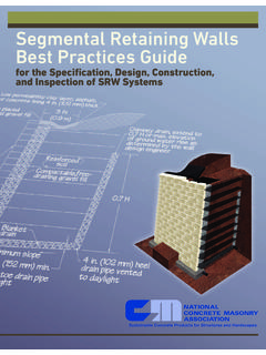
8 The most common types of reinforcement are geogrids and geotextiles, though most SRW construction to date has used geogrids. SYSTEM COMPONENTSThe basic elements of each segmental retaining wall systems are the foundation soil, leveling pad, segmental retaining wall units, retained soil, gravel fill, and for soil reinforced SRWs, the soil reinforcement. See Figure 4. This section describes the recommended materials that can be specified, it is the designer s responsibility to select the appropriate materials and design parameters depending on the site conditions and material availability. Because segmental retaining walls are designed as systems, the materials specified on the approved documents can not be exchanged without the evaluation and approval of design unitsCap unit (optional)Drainage swale (optional)Low permeability soilCompacted reinforced (infill) soil zoneCompacted common backfillSlope for positive drainageSetback/batterFinished gradeWallheight = HRetained Soil ZoneGeosynthetic reinforcementGravel fillLimit of excavationDrainage collection pipe at finish grade for daylight or per site specific requirementLeveling padFoundation soilFigure 4.
9 segmental retaining Wall System ComponentsBEST PRACTICES On engineered walls, materials can not be exchanged without the approval of the wall retaining Wall Installation GuideThis manual provides general guidelines, site specific conditions should be evaluated by qualified soil: Soil mass supporting the SRW system: leveling pad, blocks, gravel fill, reinforced soil (for soil-reinforced SRW), and any overlying surcharge. The foundation soil shall provide adequate bearing capacity to support the SRW components, retained soil influences and external surcharges BEST PRACTICES Foundation soils: Organic and expansive soils are unsuitable. Leveling pad materials: Avoid pea gravel for the leveling pad construction SRW units: Use pins, clips, adhesives express-ly fabricated for the system used.
10 Use 1 in. ( mm) minus crushed stone or granular fill for gravel the pad: Level surface consisting of either well compacted gravel or unreinforced low strength Concrete used to distribute the weight of the dry-stacked column of SRW units over a wider area and to provide a working surface during construction unless a reinforced rigid Concrete footing is called for. The leveling pad typically extends a minimum of 6 in. (152 mm) from the toe and heel (front and back) of the lowermost SRW unit and is at least 6 in. (152 mm) retaining wall units: Dry-stacked column of Concrete units that create the mass of conventional SRW structures and provide mass and structural stability at the face of reinforced soil SRW structures. The SRW units also provide a visual enhancement at the face of the wall. SRW units are required to meet or exceed the requirements of ASTM C1373, Standard Specification for Dry-Cast segmental retaining Walls Units (Ref.)