Transcription of Negative Feedback - Learn About Electronics
1 AC THEORY MODULE 1 E. COATES 2007 -2012 Negative Feedback Introduction to Negative Feedback Negative Feedback Negative Feedback is the technique of sampling some of the output of a device or system and applying it back to the input. This makes the input partly dependent on the output, and in doing so makes it possible to exert very fine control over whatever process is being carried out by the system. NFB With Everything! Negative Feedback is almost as old as machines, and is used in just About every possible process where some control over the output is necessary.
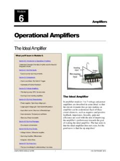
2 Cans of beans may be weighed as they come off a production line and if there is any difference between the weight measured and the ideal weight, the number of beans per can will be automatically adjusted further back in the process to maintain a constant weight. Manufacturers launching a new product will test public reaction to a small sample of their product by asking prospective buyers for their opinions, and adjust the product design as a result of the Feedback . Anything from a builder repeatedly checking that the layers of bricks are level as he builds the wall, to an aircraft landing safely at the correct point on the airport runway is an example of Feedback in action.
3 Amplifiers Module 3 What you ll Learn in Module 3. Section Introduction to NFB. The use of Negative Feedback in amplifiers. Section NFB and Gain. Controlling amplifier gain using NFB. Section NFB and Impedance. Using NFB to control Input and Output Impedance. Section NFB, and Noise. Using NFB to Reduce Noise in amplifiers. Section NFB, and Distortion. Using NFB to Reduce Distortion in amplifiers. Section NFB Quiz. Test your knowledge & understanding of Negative Feedback . Module 3 Negative Feedback AMPLIFIERS MODULE 2 E.
4 COATES 2007 - 2012 Positive and Negative Feedback There are two types of Feedback commonly used in electronic circuits, positive (regenerative) Feedback and Negative (degenerative) Feedback . Positive Feedback is primarily used in electronic oscillators, it increases gain (and distortion if not properly controlled) and narrows bandwidth to such a degree that it can be the primary reason for oscillators to work at a single frequency, rather than a band of frequencies. This module describes the application of Negative Feedback in amplifiers, where its use provides a number of very useful attributes that improve the performance of the amplifier.
5 Module 3 Negative Feedback AMPLIFIERS MODULE 3 E. COATES 2007 - 2012 Module Negative Feedback and Gain Why NFB is needed in amplifiers Transistors cannot be manufactured to have a closely controlled value of current gain hfe therefore it should not be possible to build a number of examples of the same amplifier circuit, all having the same gain. In addition the gain of a transistor varies with temperature, and even has different gain at different frequencies.
6 All of these factors would make transistor amplifiers totally unreliable and impossible to make in large numbers. The main reason that this situation does not exist, and transistor amplifiers have become the mainstay of the Electronics industry is the introduction, very early in the transistor s history, of Negative Feedback . Principle of NFB The principle of Negative Feedback is that a portion of the output signal is fed back to the input and combined with the input signal in such a way as to reduce it. This reduces the overall gain of the amplifier but also introduces a number of benefits, such as reducing distortion and noise, and widening the amplifier s bandwidth.
7 Problems with NFB Introducing Feedback within a system can also introduce the possibility of instability; in amplifiers the signal will normally undergo a phase reversal of 180 degrees between input and output but reactive components such as capacitors and inductors, whether actual components or stray capacitance and inductance, can introduce unwanted phase changes at particular (usually high) frequencies. If these additional changes add up to a further 180 degrees at any frequency where the transistor has a gain of more than 1, the application of Negative Feedback may become positive Feedback .
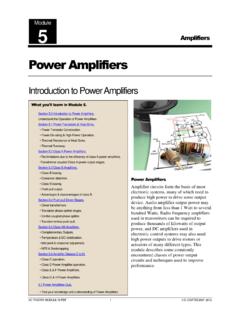
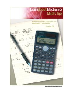
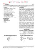
8 Instead of reducing gain this will increase it to the point where the amplifier will become an oscillator and produce unwanted signals. Negative Feedback must therefore be designed to maximise the benefits mentioned above, without creating unwanted problems. The Amplifier in Open Loop Mode Fig. shows a phase reversing voltage amplifier with gain in open loop mode with no Feedback , which can be called Ao (Amplification in open loop mode). Supposing an input signal of 1mV is applied, then the output will be an inverted (anti-phase) signal with an amplitude of 1mV x Ao = Ao(mV).
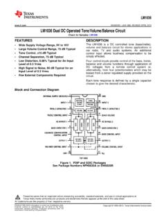
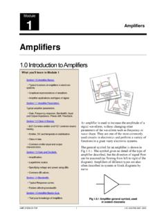
9 What you ll Learn in Module After studying this section, you should be able to: Understand the basic principles of NFB as applied to amplifiers. Open loop gain. Closed loop gain. The relationship between and gain. Reasons for using Negative Feedback . Fig. Open Loop Mode Module 3 Negative Feedback AMPLIFIERS MODULE 4 E. COATES 2007 - 2012 The Negative Feedback Amplifier in Closed Loop Mode A basic Negative Feedback arrangement is shown in Fig.
10 Where the phase reversing amplifier has a fraction of its output (Vout) fed back and added to the input (Vin) so as to reduce the amplitude of the input signal. The arrows show the relative polarity of the signals and it can be seen that the output and the Feedback signals are in anti-phase to the input signal. The fraction of the output signal to be fed back is controlled by the potential divider ( ) and this fraction is added to the input signal in anti-phase so that it is, in effect, subtracted from the input signal (Vin) to give a combined signal (Vc) that is reduced in amplitude before being fed to the actual input of the amplifier.