Transcription of Network Infrastructure - Cisco
1 CHAPTER3-1 Cisco Unified CallManager Express Solution Reference Network design GuideOL-10621-013 Network InfrastructureThis chapter describes the requirements of the Network Infrastructure needed to build an IP telephony system in an enterprise environment. Figure 3-1 illustrates the roles of the various devices that form the Network Infrastructure of a large-scale enterprise Network , and Ta b l e 3 -1 summarizes the features required to support each of these telephony places strict requirements on IP packet loss, packet delay, and delay variation (or jitter). Therefore, you need to enable most of the Quality of Service (QoS) mechanisms available on Cisco switches and routers throughout the Network .
2 For the same reasons, redundant devices and Network links that provide quick convergence after Network failures or topology changes are also important to ensure a highly available general, this document focuses on standalone and multisite Cisco Unified CallManager Express ( Cisco Unified CME) implementations. However, this chapter addresses many issues related to larger enterprise-sized networks. As such, it discusses issues related to Cisco Unified CME deployments featuring centralized call processing. This information is included for context, as Cisco Unified CME is also applicable in larger networks as part of a distributed environment. For more information, see the collection of design guides presentedat: The design guides presented there describe deployment and implementation considerations for Cisco Unified CallManager, Network Infrastructure , and other related topics.
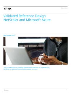
3 3-2 Cisco Unified CallManager Express Solution Reference Network design GuideOL-10621-01 Chapter 3 Network Infrastructure Figure 3-1 Typical Campus Network InfrastructureIPIPIPIPIPC entral siteCampus accesslayerCampus distributionlayerCampus corelayerBranchrouterBranchswitchWAN aggregationISDN backupPSTNB ranch offices149943IP WANIPIPIPIPIPIPIPIPMMMMIPIPIPIPMM 3-3 Cisco Unified CallManager Express Solution Reference Network design GuideOL-10621-01 Chapter 3 Network InfrastructureThe following sections describe the Network Infrastructure features as they relate to: Cisco Unified CME Network Infrastructure Overview, page 3-4 LAN Infrastructure , page 3-9 WAN Infrastructure , page 3-20 Wireless LAN Infrastructure , page 3-33 NoteFor additional information, see the Related Documents and References section on page 3-1 Required Features for Each Role in the Network InfrastructureInfrastructure RoleRequired FeaturesCampus Access Switch In-Line Power Multiple Queue Support and Fast Link ConvergenceCampus Distribution or Core Switch Multiple Queue Support and Traffic Classification Traffic ReclassificationWAN Aggregation Router(Site that is at the hub of the Network ) Multiple Queue Support Traffic Shaping Link Fragmentation and Interleaving (LFI)
4 Link Efficiency Traffic Classification Traffic Reclassification and Router(Spoke site) Multiple Queue Support LFI Link Efficiency Traffic Classification Traffic Reclassification and or Smaller Site Switch In-Line Power Multiple Queue Support and 3-4 Cisco Unified CallManager Express Solution Reference Network design GuideOL-10621-01 Chapter 3 Network Infrastructure Cisco Unified CME Network Infrastructure OverviewCisco Unified CME Network Infrastructure OverviewThis publication focuses on two Cisco Unified CME implementations: standalone and multisite deployments. The general Infrastructure considerations for networks supporting Cisco Unified CME are summarized in the following two sections: Standalone Network Infrastructure Overview, page 3-4 Multisite Network Infrastructure Overview, page 3-6 Standalone Network Infrastructure OverviewCisco Unified CME is an excellent choice for a single-site, standalone office.
5 In a world before IP telephony, such an office would have had an onsite router for data services and a separate key system or centrex for voice services. Now the router can be extended to provide converged data and voice services to the office. It also can be managed in the same way as before (either by an ISP or by a VAR or SI). Furthermore, both the business and the SP can realize cost, space, and management just in wiring of a new office could be enough to make Cisco Unified CME cost-effective. Because the phones and computer equipment are all Ethernet-based, only Ethernet wiring is required in the office. Furthermore, only a single Ethernet wire or jack is required to each employee location or desktop.
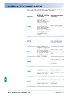
6 Computer equipment can be plugged into the back of the phone, and virtual LAN (VLAN) technology can be used to provide virtual separation (and therefore security) of voice from data productivity features and improved customer service IP-based applications, such as XML services, can also be deployed easily over this converged 3-2 shows what such a single-site office s Network might look like. 3-5 Cisco Unified CallManager Express Solution Reference Network design GuideOL-10621-01 Chapter 3 Network Infrastructure Cisco Unified CME Network Infrastructure OverviewFigure 3-2 Standalone Office Network TopologyThe Network inFigure 3-2 has the following components: Employee desktop Cisco 7960 IP Phones are provided for employees who work at a desk with a computer.
7 The PC is connected via the phone s Ethernet switch. It also is connected via a single Ethernet cable to a LAN switch that provides inline power to the phones. In Figure 3-2, the LAN switch is a separate component, but a LAN switch that optionally provides inline power can also be integrated into the router chassis for offices requiring 50 or fewer LAN connections. The ability to connect computer equipment via the phone substantially reduces the overall number of switch ports required in the office. However, this might require that an existing LAN switch be upgraded to provide inline power for the IP phones. However, inline power is not a requirement for IPT deployments. Internet connectivity This is provided via a DSL or a similar type of uplink to the local ISP, which also might host the company s e-mail services.
8 For larger offices, DSL may not have sufficient bandwidth. Internet connectivity may then be deployed via fractional T1/E1 leased-line services, or even a grouping of multiple DSL or Basic Rate Interface (BRI) lines. PSTN trunks These PSTN lines are analog Foreign Exchange Office (FXO) connections to the central office (CO). Each line carries a single incoming or outgoing phone call. Caller ID is typically delivered on such connections, but direct inward dial (DID) operation is not. A variation of this offering from the PSTN offers DID operation; this is technically known as analog DID service. It can have a different cost than the plain FXO service. The trunks can also be on a fractional T1/E1 or a full T1/E1 type of service that runs CAS or PRI services.
9 Small businesses often prefer familiar key system operation. In this system, individual PSTN lines are mapped to buttons on the phones DSLFaxCisco access router with Cisco Unified CME,voice mail, and firewall GUImanagementstationPrinterCO line 1, 2, 3, 4 Catalyst 3550-24 access switch Analog phonesWirelessaccess point Employee PC, Cisco Unified IP Phone 7960G,and voice mailCisco Unified IP Phone 7905in lobby, breakroom, orconference roomCisco Unified IP Phone 7914as the attendant consoleCisco Unified IP Phone 7920for roaming employeesIPIPIPIPIPIPVA pplicationserverPSTNP ublicInternetDial backupand POS149941 3-6 Cisco Unified CallManager Express Solution Reference Network design GuideOL-10621-01 Chapter 3 Network Infrastructure Cisco Unified CME Network Infrastructure Overviewlabeled as Line1, Line2, Line3, and so on up to the number of lines coming in from the PSTN central office.
10 (This arrangement is called key-system or square-keyswitch type of deployment.). These can also be used in the PBX-mode in which a user typically dials an access-code (like 9, commonly used in the US) for gain access to an outside PSTN line. Attendant console Many small businesses with more than a handful of employees or considerable front-office customer interaction (such as a doctor s office) prefer that an attendant or receptionist answer incoming calls. Although these businesses might use an automated attendant (AA) for after-hours coverage, the typical preferred customer interaction during normal business hours is person-to-person. Attendant consoles can be a Cisco Unified IP Phone 7960 with one or two Cisco Unified IP Phone 7914s providing a total of 34 extensions that can be monitored.