Transcription of NEW TECHNOLOGY IN DATA COMMUNICATIONS
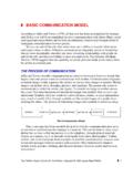
1 chapter 7 NEW TECHNOLOGY IN data COMMUNICATIONSINTRODUCTIONThe current Link-11 and Link-4A systems are being updated with new equipments. The DataTerminal Set AN/USQ-125 is currently replacing the older Link-11 data terminals. In addition, newcommunications systems, such as the Command and control Processor (C2P) and the JointTactical Information Distribution System (JTIDS), are quickly becoming commonplace onvarious platforms in the Navy. This chapter will introduce you to some of the changes taking placeand the basic features of some of the new completing this chapter , you should be able to.
2 Describe the various components of the AN/USQ-125 data Terminal Describe the operation of the AN/USQ-125 in a typical Link-11 State the purpose of the Joint Tactical Information data System (Link-16).. Describe the components of the Link-16 State the function of the Command and control Processor (C2P) Describe the components of the C2P AN/USQ-125 data TERMINAL SETThe AN/USQ-125 data terminal set is the newestLink-11 data terminal set in the Navy.
3 It is quicklyreplacing older DTSs, such as the AN/USQ-36 andthe AN/USQ-59. There are several configurations ofthe AN/USQ- 125. The CP-2205(P)(V)/USQ-125 dataterminal with the MX-512P/RC Remote control Unitconfiguration. The other configuration isCP-2205(P)(V)2/USQ-125 data terminal with apersonal computer (386 or better) running theMXPCR software. The personal computer serves theFigure 7-1. The AN/USQ-125 data terminal set standardsame function as the remote control indicator in thisinterface block The standard interface configuration ofthe AN/USQ-125 is shown in figure 7-1.
4 In thischapter, we examine the data terminal and theTHE CP-2205(P)(V)/USQ-125 data TERMINAL functions of the control indicators, either theMX-512P/RC or a personal CP-2205(P)(V)/USQ-125 data terminal is acompact, state-of-the-art data terminal that is mountedin a standard 19-inch equipment rack. The data7-1 Figure 7-2. The CP-2205(P)(V)/USQ-125 data terminal block has the following three major components: aprocessor board, a CDS interface board, and thepower supply.
5 Figure 7-2 is a block diagram of theCP-2205(P)(V)/USQ-125 data terminal. Theprocessor board performs modulation/demodulationand error detection and correction, and provides theinterface with the radio set. The CDS interface boardprovides the interface with the CDS computer. TheCP-2205(P)(V)/USQ-125 data terminal performsmany of the same functions as previous Link-11 dataterminal sets. These functions include the following: data conversionData error detection and correctionControl code generation and detectionSynchronizationEncryption device data transferComputer and radio control signals for two-way Link-11 data transfersIn addition, the CP-2205(P)(V)/USQ-125 dataterminal provides the following new features.
6 Both multi-tone and single-tone waveformoperationsEnhanced Link Quality Analysis (ELQA)Maximum useable frequency (MUF) optionMulti-Frequency LinkOn-line and Off-line System Test OptionsMulti-Tone Waveform LinkMulti-tone link operations are basically the sameas in the previous Link-11 data terminal sets and arecalled conventional Link-11 waveforms. The dataterminal generates the 605-Hz Doppler tone and 15data tones. The frequencies of the data tones are thesame as described in chapter 4.
7 Message formats andmodes are also the Waveform LinkSingle-tone waveform link updates the 1960 stechnology used in data COMMUNICATIONS . The single-ton waveform is a 1,800-Hz phase-modulatedwaveform containing the Link-11 data in a serial bitstream. The single-tone waveform is most commonlyused with the wire-line option of the USQ-125 dataterminal. The CP-2205(P)(V)/USQ-125 data terminalwire-line option provides an interface port that can beused with a standard wire-line or a satellite this option expands the means in which Link-11 data can be exchanged, overcoming the limitationsof the traditional UHF and HF radio Link Quality Analysis (ELQA)The Enhanced Link Quality Analysis option of thedata terminal incorporates almost all of the functionsof the LMS-11.
8 This allows the operator to monitorand evaluate the performance of the link that can be displayed includes the7-2following: sideband power, error rate, and percentageof interrogations Useable Frequency (MUF) OptionThe maximum useable frequency option is aroutine that calculates the optimum frequency forLink-11 operations. This routine calculates afrequency for each hour of the day based ongeographic location, the range of other participants inthe net, and sunspot LinkThe multi-frequency link option improves currentlink operations.
9 By simultaneously using fourfrequencies. The normal configuration for multi-frequency link operations uses three HF and one UHFfrequency. To implement this option, three additionalprocessor boards are installed in the data data terminal board is connected to a separateradio, as shown in figure 7-3. Block diagram of the AN/USQ-125 dataterminal configured for multi-frequency link the Link-11 receive cycle, each dataterminal board demodulates the link signal and sendsthe data to the master processor board.
10 The masterprocessor compares the received data and selects thesignals with the fewest errors to send to the CDScomputer. Although this mode is normally used withthree HF frequencies and one UHF frequency, there isno set limitation of the radio and Off-1ine System Test OptionsThe data terminal provides several options forboth on-line and off-line testing. These include thefollowing: radio echo test, loopback tests 1, 2, 3, and4, and DTS fault isolation tests.