Transcription of Nexys A7 FPGA Board Reference Manual - Digilent Reference
1 1300 Henley Court Pullman, WA 99163 Nexys A7 FPGA Board Reference Manual Revised July 10, 2019 Copyright Digilent , Inc. All rights reserved. Other product and company names mentioned may be trademarks of their respective owners. Page 1 of 33 Table of Contents Table of Contents .. 1 Features .. 4 Purchasing Options .. 6 Board Revisions .. 6 Migrating from Nexys 4 DDR .. 6 Migrating from Nexys 4 .. 7 1 Functional Description .. 7 Power Supplies .. 7 Protection .. 8 2 FPGA Configuration .. 8 JTAG Configuraiton .. 9 Quad-SPI Configuration .. 10 USB Host and Micro SD Programming .. 10 3 Memory .. 11 DDR2 .. 11 Quad-SPI Flash .. 12 4 Ethernet PHY .. 12 Nexys A7 FPGA Board Reference Manual Copyright Digilent , Inc. All rights reserved. Other product and company names mentioned may be trademarks of their respective owners. Page 2 of 33 5 Oscillators/Clocks.
2 13 6 USB-UART Bridge (Serial Port) .. 14 7 USB HID Host .. 14 HID Controller .. 15 Keyboard .. 16 Mouse .. 17 8 VGA Port .. 18 VGA System Timing .. 18 9 Basic I/O .. 22 Seven-Segment Display .. 23 Tri-Color LED .. 24 10 Pmod Ports .. 25 Dual Analog/Digital Pmod .. 25 11 MicroSD Slot .. 26 12 Temperature 26 I2C Interface .. 27 Open Drain Outputs .. 27 Quick Start Operation .. 27 13 Accelerometer .. 27 SPI Interface .. 28 Interrupts .. 28 14 Microphone .. 28 Pulse Density Modulation (PDM) .. 29 Microphone Digital Interface Timing .. 30 Nexys A7 FPGA Board Reference Manual Copyright Digilent , Inc. All rights reserved. Other product and company names mentioned may be trademarks of their respective owners. Page 3 of 33 15 Mono Audio Output .. 30 Pulse-Width Modulation .. 31 Built-In Self-Test .. 32 Nexys A7 FPGA Board Reference Manual Copyright Digilent , Inc.
3 All rights reserved. Other product and company names mentioned may be trademarks of their respective owners. Page 4 of 33 Features The Nexys A7 Board is a complete, ready-to-use digital circuit development platform based on the latest Artix-7 Field Programmable Gate Array (FPGA) from Xilinx . With its large, high-capacity FPGA, generous external memories, and collection of USB, Ethernet, and other ports, the Nexys A7 can host designs ranging from introductory combinational circuits to powerful embedded processors. Several built-in peripherals, including an accelerometer, temperature sensor, MEMs digital microphone, a speaker amplifier, and several I/O devices allow the Nexys A7 to be used for a wide range of designs without needing any other components. The Nexys A7 FPGA. The Nexys A7-100T is compatible with Xilinx s Vivado Design Suite as well as the ISE toolset, which includes ChipScope and EDK.
4 Xilinx ISE has been discontinued in favor of Vivado Design Suite. The Nexys A7-50T variant is compatible only with Vivado Design Suite. Xilinx offers free WebPACK versions of these toolsets, so designs can be implemented at no additional cost. Artux-7 FPGA o 15,850 Programmable logic slices, each with four 6-input LUTs and 8 flip-flops (*8,150 slices) o 1,188 Kbits of fast block RAM (*600 Kbits) o Six clock management tiles, each with phase-locked loop (PLL) o 240 DSP slices (*120 DSPs) o Internal clock speeds exceeding 450 MHz o Dual-channel, 1 MSPS internal analog-digital converter (XADC) Memory o 128 MiB DDR2 o Serial Flash o microSD card slot Power o Powered from USB or any external power source USB and Ethernet o 10/100 Ethernet PHY o USB-JTAG programming circuitry o USB-UART bridge o USB HID Host for mice, keyboards and memory sticks Simple User Input/Output o 16 Switches o 16 LEDs o Two RGB LEDs o Two 4-digit 7-segment displays Audio and Video o 12-bit VGA output o PWM audio output o PDM microphone Additional Sensors o 3-axis accelerometer o Temperature sensor Expansion Connectors o Pmod connector for XADC signals o Four Pmod connectors providing 32 total FPGA I/O Nexys A7 FPGA Board Reference Manual Copyright Digilent , Inc.
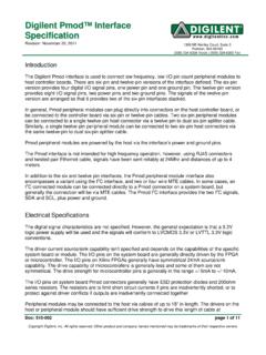
5 All rights reserved. Other product and company names mentioned may be trademarks of their respective owners. Page 5 of 33 The Nexys A7 is not supported by the Digilent Adept Utility. Figure 1. Nexys A7 Feature Callout. Callout Component Description Callout Component Description 1 Power jack 16 JTAG port for (optional) external cable 2 Power switch 17 Tri-color (RGB) LEDs 3 USB host connector 18 Slide switches (16) 4 PIC24 programming port (factory use) 19 LEDs (16) 5 Ethernet connector 20 Power supply test point(s) 6 FPGA programming done LED 21 Eight digit 7-seg display 7 VGA connector 22 Microphone 8 Audio connector 23 External configuration jumper (SD / USB) 9 Programming mode jumper 24 MicroSD card slot 10 Analog signal Pmod port (XADC) 25 Shared UART/ JTAG USB port Nexys A7 FPGA Board Reference Manual Copyright Digilent , Inc. All rights reserved. Other product and company names mentioned may be trademarks of their respective owners.
6 Page 6 of 33 Purchasing Options The Nexys A7 can be purchased with either a XC7A100T or XC7A50T FPGA loaded. These two Nexys A7 product variants are referred to as the Nexys A7-100T and Nexys A7-50T, respectively. When Digilent documentation describes functionality that is common to both of these variants, they are referred to collectively as the Nexys A7 . When describing something that is only common to a specific variant, the variant will be explicitly called out by its name. The only difference between the Nexys A7-100T and Nexys A7-50T is the size of the Artix-7 part. The Artix-7 FPGAs both have the same capabilities, but the XC7100T has about a 2 times larger internal FPGA than the XC750T. The differences between the two variants are summarized below: Board Revisions The Nexys A7 is a rebrand of the Nexys 4 DDR Board , which is an incremental update to the Nexys 4 Board .
7 Migrating from Nexys 4 DDR The only difference between the Nexys A7 and Nexys 4 DDR is the addition of the Nexys A7-50T variant of the Nexys A7, which has a smaller gate array. The Nexys A7-100T variant is functionally identical to the Nexys 4 DDR. Users of the Nexys A7 may find resources produced for the Nexys 4 DDR helpful, which can be found at the Nexys 4 DDR's Resource Center. 11 FPGA configuration reset button 26 Power select jumper and battery header 12 CPU reset button (for soft cores) 27 Power-good LED 13 Five pushbuttons 28 Xilinx Artix-7 FPGA 14 Pmod port(s) 29 DDR2 memory 15 Temperature sensor Product Variant Nexys A7-100T Nexys A7-50T FPGA Part Number XC7A100T-1 CSG324C XC7A50T-1 CSG324I Look-up Tables (LUTs) 63,400 32,600 Flip-Flops 126,800 65,200 Block RAM 1,188 Kb 600 Kb DSP Slices 240 120 Clock Management Tiles 6 5 Nexys A7 FPGA Board Reference Manual Copyright Digilent , Inc.
8 All rights reserved. Other product and company names mentioned may be trademarks of their respective owners. Page 7 of 33 Migrating from Nexys 4 The major improvement from the Nexys 4 to the Nexys 4 DDR is the replacement of the 16 MiB Cellular RAM with a 128 MiB DDR2 SDRAM memory. Furthermore, to accommodate the new memory, the pin-out of the FPGA banks changed as well. The audio output (AUD_PWM) needs to be driven open-drain as opposed to push - pull on the Nexys 4. 1 Functional Description Power Supplies The Nexys A7 Board can receive power from the Digilent USB-JTAG port (J6) or from an external power supply. Jumper JP3 (near the power jack) determines which source is used. All Nexys A7 power supplies can be turned on and off by a single logic-level power switch (SW16). A power-good LED (LD22), driven by the power good output of the ADP2118 supply, indicates that the supplies are turned on and operating normally.
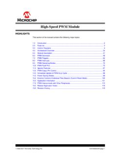
9 An overview of the Nexys A7 power circuit is shown in Figure Figure Nexys A7 Power Circuit The USB port can deliver enough power for the vast majority of designs. In order to power the Board from USB port set jumper JP3 to USB . Our out-of-box demo draws ~400mA of current from the 5V input rail. A few demanding applications, including any that drive multiple peripheral boards, might require more power than the USB port can provide. Also, some applications may need to run without being connected to a PC s USB port. In these instances, an external power supply or battery pack can be used. Nexys A7 FPGA Board Reference Manual Copyright Digilent , Inc. All rights reserved. Other product and company names mentioned may be trademarks of their respective owners. Page 8 of 33 An external power supply can be used by plugging into to the power jack (J13) and setting jumper JP3 to WALL.
10 The supply must use a coax, center-positive internal-diameter plug, and deliver to and at least 1A of current ( , at least 5W of power). Many suitable supplies can be purchased from Digilent , through Digi-Key, or other catalog vendors. An external battery pack can be used by connecting the battery s positive terminal to the center pin of JP3 and the negative terminal to the pin labeled J12, directly below JP3. Since the main regulator on the Nexys A7 cannot accommodate input voltages over , an external battery pack must be limited to The minimum voltage of the battery pack depends on the application: if the USB Host function (J5) is used, at least needs to be provided. In other cases, the minimum voltage is Voltage regulator circuits from Analog Devices create the required , , and supplies from the main power input. Table provides additional information.