Transcription of Omni ision Preliminary Datasheet Advanced Information
1 2006 OmniVision Technologies, , VarioPixel, OmniVision, and the OmniVision logo are registered trademarks of OmniVision Technologies, , August 21, 2006 CameraChip is a trademark of OmniVision Technologies, specifications are subject to change without InformationPreliminary DatasheetOV7670/OV7171 CMOS VGA (640x480) CAMERACHIPTM SensorOmniision with OmniPixel TechnologyGeneral Description The OV7670/OV7171 CAMERACHIPTM image sensor is a lowvoltage CMOS device that provides the full functionality of asingle-chip VGA camera and image processor in a smallfootprint package. The OV7670/OV7171 provides full-frame,sub-sampled or windowed 8-bit images in a wide range offormats, controlled through the Serial Camera Control Bus(SCCB) product has an image array capable of operating at upto 30 frames per second (fps) in VGA with complete usercontrol over image quality, formatting and output datatransfer.
2 All required image processing functions, includingexposure control, gamma, white balance, color saturation,hue control and more, are also programmable through theSCCB interface. In addition, OmniVision sensors useproprietary sensor technology to improve image quality byreducing or eliminating common lighting/electrical sources ofimage contamination, such as fixed pattern noise (FPN),smearing, blooming, etc., to produce a clean, fully stablecolor High sensitivity for low-light operation Low operating voltage for embedded portable apps Standard SCCB interface compatible with I2C interface Output support for Raw RGB, RGB (GRB 4:2:2, RGB565/555/444), YUV (4:2:2) and YCbCr (4:2:2) formats Supports image sizes: VGA, CIF, and any size scaling down from CIF to 40x30 VarioPixel method for sub-sampling Automatic image control functions including.
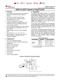
3 Automatic Exposure Control (AEC), Automatic Gain Control (AGC), Automatic White Balance (AWB), Automatic Band Filter (ABF), and Automatic Black-Level Calibration (ABLC) Image quality controls including color saturation, hue, gamma, sharpness (edge enhancement), and anti-blooming ISP includes noise reduction and defect correction Supports LED and flash strobe mode Supports scaling Lens shading correction Flicker (50/60 Hz) auto detection Saturation level auto adjust (UV adjust) Edge enhancement level auto adjust De-noise level auto adjustOrdering Information Pb Note: The OV7670/OV7171 uses a lead-free (Color, lead-free)24 pin CSP2OV07171-VL2A (B&W, lead-free)24 pin CSP2 Applications Cellular and Picture Phones Toys PC Multimedia Digital Still CamerasKey Specifications Figure 1 OV7670/OV7171 Pin Diagram (Top View)Active Array Size640 x 480 Power SupplyDigital +10% to to I/O power should be or higher when using the internalregulator for Core ( ).
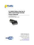
4 Otherwise, it is necessary to providean external for the Core power mW typical(15fps VGA YUV format)Standby< 20 ATemperatureRangeOperation-30 C to 70 CStable Image0 C to 50 COutput Formats (8-bit) YUV/YCbCr 4:2:2 RGB565/555/444 GRB 4:2:2 Raw RGB DataLens Size1/6"Chief Ray Angle25 Maximum ImageTransfer Rate30 fps for V/(Lux sec)S/N Ratio46 dBDynamic Range52 dBScan ModeProgressiveElectronics ExposureUp to 510:1 (for selected fps)Pixel m x mDark Current12 mV/s at 60 CWell Capacity17 K eImage mm x mmPackage Dimensions3785 m x 4235 mOV7670/OV7171 AGNDSIO_CA1A2A4A3D1D0D3D2A5B1B2B4B3B5C1D 1D2 AVDDSIO_DPWDNVSYNCVREF2 HREFDVDDC2 VREF1D4D5E1E2E4E3E5F1F2F4F3F5 DOGNDDOVDDPCLKSTROBERESET#D6 XCLKD77670 CSP_DS_0012 Proprietary to OmniVision Technologies, , August 21, 2006OV7670/OV7171 CMOS VGA (OmniPixel ) CAMERACHIP SensorOmniisionFunctional Description Figure 2 shows the functional block diagram of the OV7670/OV7171 image sensor.
5 The OV7670/OV7171 includes: Image Sensor Array (total array of 656 x 488 pixels, with active pixels 640 x 480 in YUV mode) Analog Signal Processor A/D Converters Test Pattern Generator Digital Signal Processor (DSP) Image Scaler Timing Generator Digital Video Port SCCB Interface LED and Strobe Flash Control OutputFigure 2 Functional Block DiagramA/DGD[7:0]BR50/60 HzAutoDetectTestPatternGeneratorVideoPor tImageScalerDSPB ufferBuffer(Lens shading correction, de-noise, white/ black pixel correction, auto white balance, etc.)FIFOA nalogProcessingImage Array(656 x 488)Column Sense AmpExposure/GainDetectExposure/GainContr olSCCBI nterfaceRegistersVideo Timing GeneratorClockSIO_CSIO_DSTROBEPWDNRESET# VSYNCPCLKHREFXCLKRow Select7670 CSP_DS_002 Functional DescriptionVersion , August 21, 2006 Proprietary to OmniVision Technologies, Sensor ArrayThe OV7670/OV7171 sensor has an image array of656 x 488 pixels for a total of 320,128 pixels, of which640 x 480 pixels are active (307,200 pixels).
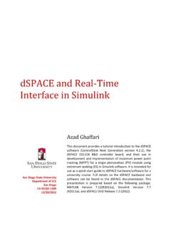
6 Figure 3shows a cross-section of the image sensor 3 Image Sensor ArrayTiming GeneratorIn general, the timing generator controls the followingfunctions: Array control and frame generation Internal timing signal generation and distribution Frame rate timing Automatic Exposure Control (AEC) External timing outputs (VSYNC, HREF/HSYNC, and PCLK)Analog Signal ProcessorThis block performs all analog image functions including: Automatic Gain Control (AGC) Automatic White Balance (AWB)A/D ConvertersAfter the Analog Processing block, the bayer pattern Rawsignal is fed to a 10-bit analog-to-digital (A/D) convertershared by G and BR channels. This A/D converteroperates at speeds up to 12 MHz and is fully synchronousto the pixel rate (actual conversion rate is related to theframe rate).
7 In addition to the A/D conversion, this block also has thefollowing functions: Digital Black-Level Calibration (BLC) Optional U/V channel delay Additional A/D range controlsIn general, the combination of the A/D Range Multiplierand A/D Range Control sets the A/D range and maximumvalue to allow the user to adjust the final image brightnessas a function of the individual Pattern GeneratorThe Test Pattern Generator features the following: 8-bar color bar pattern Fade-to-gray color bar pattern Shift "1" in output pinDigital Signal Processor (DSP)This block controls the interpolation from Raw data toRGB and some image quality control. Edge enhancement (a two-dimensional high pass filter) Color space converter (can change Raw data to RGB or YUV/YCbCr) RGB matrix to eliminate color cross talk Hue and saturation control White/black pixel correction De-noise Lens shading correction Programmable gamma control Transfer 10-bit data to 8-bitImage ScalerThis block controls all output and data formatting requiredprior to sending the image out.
8 This block scalesYUV/RGB output from VGA to CIF and almost any sizeunder Video PortRegister bits COM2[1:0] increase IOL/IOH drive currentand can be adjusted as a function of the customer InterfaceThe Serial Camera Control Bus (SCCB) interface controlsthe CAMERACHIP sensor operation. Refer to OmniVisionTechnologies Serial Camera Control Bus (SCCB)Specification for detailed usage of the serial control and Strobe Flash Control OutputThe OV7670/OV7171 has a Strobe mode that allows it towork with an external flash and DescriptionVersion , August 21, 2006 Proprietary to OmniVision Technologies, Description Table 1 Pin DescriptionPin NumberNamePin TypeFunction/DescriptionA1 AVDDP owerAnalog power supplyA2 SIO_DI/OSCCB serial interface data I/OA3 SIO_CInputSCCB serial interface clock inputA4D1aa.
9 D[7:0] for 8-bit YUV or RGB (D[7] MSB, D[0] LSB)OutputYUV/RGB video component output bit[1]A5D3 OutputYUV/RGB video component output bit[3]B1 PWDNI nput (0)bb. Input (0) represents an internal pull-down Down Mode Selection0: Normal mode1: Power down modeB2 VREF2 ReferenceReference voltage - connect to ground using a F capacitorB3 AGNDP owerAnalog groundB4D0 OutputYUV/RGB video component output bit[0]B5D2 OutputYUV/RGB video component output bit[2]C1 DVDDP owerPower supply (+ VDC) for digital logic coreC2 VREF1 ReferenceReference voltage - connect to ground using a F capacitorD1 VSYNCO utputVertical sync outputD2 HREFO utputHREF outputE1 PCLKO utputPixel clock outputE2 STROBEO utputLED/strobe control outputE3 XCLKI nputSystem clock inputE4D7 OutputYUV/RGB video component output bit[7]E5D5 OutputYUV/RGB video component output bit[5]F1 DOVDDP owerDigital power supply for I/O ( ~ )
10 F2 RESET#InputClears all registers and resets them to their default : Reset mode1: Normal modeF3 DOGNDP owerDigital groundF4D6 OutputYUV/RGB video component output bit[6]F5D4 OutputYUV/RGB video component output bit[4]5 Proprietary to OmniVision Technologies, , August 21, 2006OV7670/OV7171 CMOS VGA (OmniPixel ) CAMERACHIP SensorOmniisionElectrical Characteristics NOTE:Exceeding the Absolute Maximum ratings shown above invalidates all AC and DC electrical specifications and mayresult in permanent device 2 Absolute Maximum RatingsAmbient Storage Temperature -40 C to +95 CSupply Voltages (with respect to Ground) VVDD-C3 VAll Input/Output Voltages (with respect to Ground) to VDD-IO+ Temperature, Surface-mount process245 CTable 3 DC Characteristics (-30 C < TA < 70 C)SymbolParameterConditionMinTypMaxUnitV DD-ADC supply voltage Analog supply voltage Digital Core supply voltage I/O power (Operating) CurrentSee Note aa.