Transcription of Only America North - Emerson
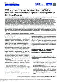
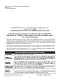
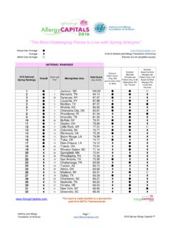
1 Instruction Manual 2000 and 2500 Series May 2016. 2000 and 2500 Series Emergency Pressure Relief Vents (ATEX Approved). Table of Contents 1. 2. Product Identification and 2 P1888. Principle of 4. Figure 1. 2000 Series Emergency Pressure Relief Vent 6. 7. ! Warning North America Only Failure to follow these instructions or to properly install and maintain this equipment could result in an explosion, P1890. fire and/or chemical contamination Figure 2. 2500 Series Emergency Pressure Relief Vent causing property damage and personal with Vacuum injury or death. Enardo emergency pressure relief vent must be installed, operated and maintained in accordance with federal, state and local codes, rules and regulations, and Emerson Process Management Regulator Technologies Tulsa, LLC (EmersonTM) instructions . Failure to correct trouble could result in a hazardous condition. Call a qualified service person to service the unit. Figure 3. 2000 Series with Smart Wireless Monitoring Installation, operation and maintenance procedures performed by unqualified Introduction person may result in improper adjustment and unsafe operation.
2 Either condition Scope of the Manual may result in equipment damage or personal injury. Only a qualified person This Instruction Manual provides instructions shall install or service the emergency for installation and maintenance for the 2000 and pressure relief vent. 2500 Series emergency pressure relief vents (EPRVs). D103817X012. 2000 and 2500 Series Specifications The Specifications section lists the specifications for the 2000 and 2500 Series. Specification is stamped on the nameplate attached to the emergency relief vent. Refer to Product Identification and Marking section for the nameplate details. Connection Sizes Available Vacuum Pressure Ranges(1) (2500 Series). See Table 1 , , 1 and 2 in. Pressure Ranges(1)(2) Construction Materials 2000 Series: 2000 Series to in. Base and Arm: Carbon Steel, 304 Stainless steel ( in. increments) and 316 Stainless steel to in. Disk and Seal Support: Aluminum, ( in. increments) 304 Stainless steel and 316 Stainless steel to 138 mbar Seal: Buna-N, FEP Teflon and Viton.
3 ( mbar increments). 2500 Series 2500 Series: Base, Arm and Hood: Carbon steel, to in. 304 Stainless steel and 316 Stainless steel ( in. increments) Disk and Seal Support: Aluminum and to in. 316 Stainless steel ( in. increments) Seal: FEP Teflon , Viton and Buna-N. North America Only to mbar Vacuum Spring: 302 Stainless steel ( mbar increments) Vacuum Pallet and Vacuum Seat: Polyphenylene Sulfide and 316 Stainless steel 1. The pressure limits in this Instruction Manual and any applicable standard or code limitation should not be exceeded. II 1 G c T6 Outer housing of stainless steel, carbon steel or coated aluminum II 2 G c T6 Outer housing of uncoated aluminum II 1 G c T5 smart wireless id marking Ex ia IIC T5 Ga (2000 series models only). HAZARDOUS LOCATION. Figure 4. Product Identification and Marking Table 1. Connection sizes and Model Number Connection Size SERIES Model ANSI API. 2004 4 in. ---- 2008 8 in. 8 in. 2012 12 in. ---- 2000 Series Emergency Pressure Relief - 2016 16 in.
4 ---- For Pressure Relief Only 2018 18 in. ---- 2020 20 in. 20 in. 2024 24 in. 24 in. 2500 Series 2516 16 in. ---- Emergency Pressure Relief Vent 2520 20 in. 20 in. with Vacuum - For Pressure and Vacuum Relief 2524 24 in. 24 in. Teflon and Viton are marks owned by E. I. du Pont de Nemours and Company. 2. 2000 and 2500 Series 2 0 . Series Connection Base and Disk Cover Gasket Bolt Pressure Options Size Arm Pattern Settings (4, 8, 12, 16, 2=C arbon 1 = Aluminum T = Teflon 1 = ANSI n = in. 1 = Special 18, 20 and Steel 3 = 304 Stainless N = Buna-N 2 = API z = in. Coating 24 in.) 3=3 04 Stainless Steel V = Viton to in. 2 = Optional Steel 4 = 316 Stainelss X = Special ( in. Hardware 4=3 16 Stainless Steel increments) 3 = Other Steel 5 = Exotic 4 = Smart to in. 5 = Exotic Wireless ( in. Monitoring increments). to 138 mbar ( mbar increments). 2000 Series 2 5 / . Series Connection Base, Arm Disk and Vacuum Pallet Gasket Bolt Pressure Vacuum Options Size and Hood Seal Support and Seat Seal Pattern Settings Settings (16, 20 and 1 = Carbon Steel 1 = Aluminum 1=P olyphenylene T = Teflon 1 = ANSI n = in.)
5 , 1 = Special 24 in.) 2 = 304 Stainless 2 = 316 Stainless Sulfide N = Buna-N 2 = API z = in. , Coating Steel Steel 2=3 16 Stainless V = Viton to in. or 2 = Optional 3 = 316 Stainless 3 = Exotic Steel X = Special ( in. Hardware Steel 3 = Exotic increments) 3 = Other North America Only 4 = Exotic to in. ( in. increments). to mbar ( mbar increments). 2500 Series Figure 5. Emergency Pressure Relief Vent Model Number Product Description remote site. Under normal conditions, the emergency vent should be Closed. An Open indication can alert Emergency pressure relief vents are designed to personnel that there is a potential safety or emissions provide an emergency pressure relief opening for issue that should be further investigated. storage tanks when exposed to overpressures that are not handled by standard tank vents. 2000 Series emergency pressure relief vent (EPRV). Product Identification and Marking provides pressure relief only. 2500 Series emergency pressure relief vent with vacuum (EPRV-V) provides Hazardous Locations pressure and vacuum relief.
6 Enardo Emergency Pressure Relief Vents are Properly-sized 2000 and 2500 Series meet the API available with outer housings of carbon steel, stainless standard 2000 for emergency venting due to fire steel or aluminum as indicated in Figure 4. exposure. 2500 Series handles high capacity vacuum The following information is stamped on the nameplate flow for emergency pump-out of product. These attached to the relief valve: Model number, Flange size vents provide quick easy access for tank inspection and rating, Serial number, Tag number, Notified body and maintenance. number, Category number, year, certificate number, pressure setting and flow rate and vacuum setting and Remote Monitoring Option flow rate. The Smart Wireless monitoring option is available with the Enardo 2000 Series. It allows the detection of the Open or Closed position of the emergency vent from a Teflon and Viton are marks owned by E. I. du Pont de Nemours and Company. 3. 2000 and 2500 Series Pressure Flow North America Only Vacuum Flow Figure 6.
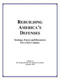
7 Pressure and Vacuum Flow Principle of Operation Refer to Figure 6. The 2000 and 2500 Series maintain a It is important to note that relieving vapors near the tight seal until system pressure or vacuum exceeds the set pressure in a continuous manner may cause the set pressure of the vent. To adjust the set pressure, a lid assembly to flutter or oscillate. This is a common series of weights may be stacked onto the lid assembly. occurrence in products of this type in the industry. When overpressure occurs, the weighted lid assembly Operating the vent with flutter or oscillation over time lifts, breaking the seal between the seat and seal may cause premature vent damage or wear. Contact portion of the lid assembly. This allows vapors to pass your local Sales Office for additional assistance. through the vent orifice and relieve pressure build up. The vent reseals upon relief and remains sealed. 4. 2000 and 2500 Series CENTER BOLT. REINFORCEMENT DISC. ARM. HINGE EAR VENT COVER.
8 PRESSURE SEAL. BASE SEAL. ASSEMBLY SUPPORT. 2000 Series Emergency Pressure Relief Vent (EPRV). GUIDE SLEEVE. VACUUM SPRING. VENT ROD. WEATHER. HOOD. ARM. North America Only HINGE. VENT COVER. PRESSURE SEAL. BASE VACUUM SEAL. VACUUM. ASSEMBLY SEAT SUPPORT. SEAL VACUUM. PALLET. 2500 Series Emergency Relief Vent with Vacuum (EPRV-V). Figure 7. 2000 and 2500 Series Assembly Drawing Remote Monitoring Option The Smart Wireless option for the 2000 Series consists protocol. It is the most widely used wireless networking of the EPRV, a proximity sensor, and a wireless standard used today and, for this reason, the transmitter. The built-in proximity sensor detects the 2000 Series has been designed to integrate with it. As open or closed position using a magnetic target located long as the wireless gateway is WirelessHART , it will on the arm assembly on the hinged end. A signal is sent receive the Open or Closed signal from the device. The to the wireless transmitter, which can then be sent to WirelessHART gateway will then send the information a control room via any WirelessHART Gateway.
9 This to a control room which can make use of any number of wireless sensor networking technology is based on software integration packages. the Highly Addressable Remote Transducer (HART ). HART and WirelessHART are marks owned by FieldComm Group. 5. 2000 and 2500 Series TRANSMITTER. CONDUIT. BRACKET. SENSOR. WIRELESS EAR. MAGNETIC TARGET. North America Only Figure 8. Enardo 2000 Smart Wireless Monitoring Option Installation 2. Carefully remove the 2000 and 2500 Series from ! Warning its crate. The seal portion of the vents is delicate, The EPRV Series is shipped with its lid protect this surface while handling the unit. held partially open. The lid assembly has 3. Place the appropriate gasket on the level attachment attached weights and is heavy. Use caution flange and center the vent into place. when removing the shipping blocks and metal bands to avoid injury to fingers 4. Insert the appropriate number of bolts and make sure and hands. the vent is fastened securely.
10 Installed bolts should be clear of the lid assembly when it is in the full Before installing the relief vent, remove the unit from open position. its crate and discard any protective coverings. Follow the instruction below for the installation of the 2000 and 5. Inspect the installed unit from items that would keep 2500 Series. it from working properly. The sealing area should be free of any debris that would cause leakage. The arm 1. Install the 2000 and 2500 Series on the flange of the vent should be able to fully open. bolt patterns that match with bolt pattern of the vent. The attachment flange base should be at level surface. 6. 2000 and 2500 Series Maintenance ! Warning Always make sure that the tank is at atmospheric pressure before opening. pressure build-up inside the tank can cause a spray to be emitted from the vent if opened under pressure. Follow the instruction below for the preventive maintenance of the 2000 and 2500 Series. 3. Replace the spring chamber and hood.