Transcription of OP-AMP Filter Examples
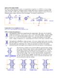
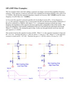
1 OP-AMP Filter Examples : The two Examples below show how adding a capacitor can change a non-inverting amplifiers frequency response. If the capacitor is removed you're left with a standard non-inverting amplifier with a gain of 10. (1 + R2/R1). Recall that the capacitors impedance depends on frequency (Xc = 1/(2 fC)) and the corner frequency of an RC Filter is fc = 1/(2 RC). In first circuit the capacitor is placed in parallel with the feedback resistor (R2). At low frequencies (f << fc) the capacitors impedance (Xc) is much greater than R2 and therefore the parallel combination of R2 & Xc is about R2 ( R2|| Xc = R2 when f << fc ). As frequency increases towards the corner frequency the impedance of the capacitor decreases and becomes comparable to that of the resistor. This lowers the impedance of the parallel combination of R2 & Xc and therefore the gain begins decreasing. When f >> fc, R2|| Xc = Xc causing the gain to drop. In this case the gain bottoms out at one since the gain equation is 1 + R2/R1.
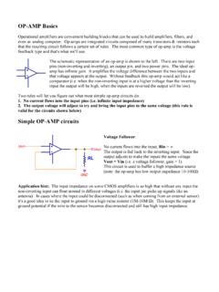
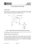
2 The second circuit has the capacitor in series with R1. When f << fc the capacitors reactance is large and R1 + Xc = Xc. Therefore the gain is 1 + R2/ Xc which = 1 when Xc >> R2. When f >> fc the capacitors reactance is small and R1 + Xc = R1. Therefore the gain is 1 + R2/ R1 which = 10 when Xc << R1. Vin Vin Vout Vout R2 R2. 9K 9K. C1. C2 R1. R1 1K. 1K. Non-Inverting Amp Non-Inverting Amp GND. High Pass Filter GND. Low Pass Filter Gain (db) Gain (db). 20 20. 0 0. Freq (Hz) Freq (Hz). 177 16K. High and low pass filters can be made by adding capacitors to inverting amplifiers as well. The first circuit is a low pass Filter . At low frequencies the capacitors impedance is high, much higher than R2, and therefore doesn't affect the circuit (XC||R2 = R2). At high frequencies the capacitors impedance is low, much lower than R2, and therefore limits the impedance of the parallel combination (XC||R2 = XC). Since the gain equation for a non-inverting amp is R2/R1 the gain doesn't bottom out at one.
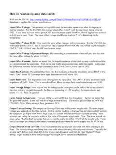
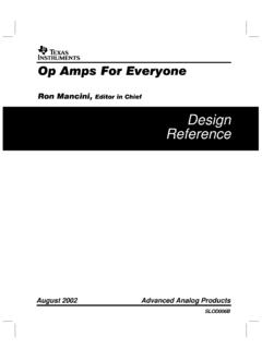
3 The gain continues to decrease as frequency increases beyond the cutoff frequency. The second circuit is a high pass Filter . At low frequencies (below the cutoff frequency) the capacitors impedance is high, much higher than R1, and therefore R1 + XC = XC. The gain is therefore R2/XC. At high frequencies the capacitors impedance is low, much lower than R1, and therefore R1 + XC = R1. The gain is therefore R2/R1. C2. R2 R2. 10K 10K. R1 C1 R1.. Vin Vin 1K Vout 1K Vout GND GND. Inverting Amp Gain (db). Gain (db) High Pass Filter Inverting Amp 20 Low Pass Filter 20. 0 Freq (Hz). 0 Freq (Hz) 160 160 The low pass and high pass Filter can be combined into a band pass Filter . In the Examples below the corner frequencies were chosen to be the audio band (20Hz 20 KHz). Notice the difference in the gain outside of the pass band. The gain of the inverting amplifier continues to drop as you get farther away from the pass band. The gain of the non-inverting amplifier only drops to 1 (0db).
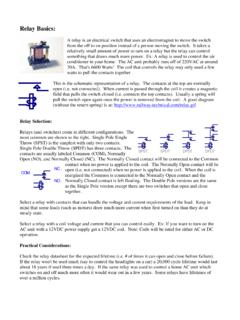
4 C2. Vin Vout 80pF. Inverting Amp R2. Band Pass Filter R2. 100K. 9K. C1 R1 C2.. Vin 10K Vout C1. 8uF. GND Non-Inverting Amp R1. 1K Band Pass Filter Gain (db) GND. Gain of 10 in audio band Gain (db). 20 20. Freq (Hz). 0. 0. 2 20 20K 200K 2 20 20K 200K Freq (Hz). Gain of 10 in audio band Each gain stage can be combined with another for a larger gain and a steeper roll-off of the frequency. C2. C4. 80pF. 80pF. R2. R4. 100K. 100K. C1 R1.. C3 R3. Vin . 10K. 10K Vout GND. GND. Gain (db) Gain of 100 in audio band 40. 20. Freq (Hz). 0. 2 20 20K 200K.