Transcription of openings - UPM
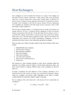
1 heat EXCHANGERS. heat exchangers: 1. Plate heat exchangers .. 4. Shell-and-tube heat exchangers .. 5. Boilers .. 6. Characteristics .. 8. heat exchanger analysis .. 10. Overall heat -transfer coefficient .. 10. Fouling .. 11. heat exchanger modelling .. 12. Non-dimensional method of heat -exchanger modelling: the NTU approach .. 15. Preliminary sizing .. 17. heat EXCHANGERS: TYPES. heat exchangers are off-the-shelf equipment targeted to the efficient transfer of heat from a hot fluid flow to a cold fluid flow, in most cases through an intermediate metallic wall and without moving parts. We here focus on the thermal analysis of heat exchangers, but proper design and use requires additional fluid- dynamic analysis (for each fluid flow), mechanical analysis (for closure and resistance), materials compatibility, and so on. heat losses or gains of a whole heat exchanger with the environment can be neglected in comparison with the heat flow between both fluid flows ; a heat exchanger can be assumed globally adiabatic.
2 Thermal inertia of a heat exchanger is often negligible too (except in special cases when a massive porous solid is used as intermediate medium), and steady state can be assumed, reducing the generic energy balance to: openings = W + Q + ht,e dme 0 = m 1 h1 + m 2 h2 (1). time where the total enthalpy ht has been approximated by enthalpy ( negligible mechanical energy against thermal energy), and means output minus input. Although heat flows from hot fluid to cold fluid by thermal conduction through the separating wall (except in direct-contact types), heat exchangers are basically heat convection equipment, since it is the convective transfer what governs its performance. Convection within a heat exchanger is always forced, and may be with or without phase change of one or both fluids. When one just relies in natural convection to the environment, like in the space-heating hot-water home radiator, or the domestic fridge back-radiator, they are termed 'radiators' (in spite of convection being dominant), and not heat exchangers.
3 When a fan is used to force the flow of ambient air (or when natural heat exchangers page 1. or artificial wind applies, like for car radiator) the name heat exchanger is often reserved for the case where the ambient fluid is ducted. Other names are used for special cases, like condenser' for the case when one fluid flow changes from vapour to liquid, vaporiser' (or evaporator, or boiler) when a fluid changes from liquid to vapour, or the cooling tower' dealt with below. Devices with just one fluid flow (like a solar collector, a spacecraft radiator, a submerged electrical heater, or a simple pipe with heat exchange with the environment) are never named heat exchangers. The basic designs for heat exchangers are the shell-and-tube heat exchanger and the plate heat exchanger, although many other configurations have been developed. According to flow layout, heat exchangers are grouped in: Shell-and-tube heat exchanger (STHE), where one flow goes along a bunch of tubes and the other within an outer shell, parallel to the tubes, or in cross-flow (Fig.)
4 1a shows a typical example of STHE; details presented below). Plate heat exchanger (PHE), where corrugated plates are held in contact and the two fluids flow separately along adjacent channels in the corrugation (Fig. 1b shows details of the interior of a PHE; more details are presented below). Open-flow heat exchanger, where one of the flows is not confined within the equipment (or at least, like in Fig. 1c, not specifically piped). They originate from air-cooled tube-banks, and are mainly used for final heat release from a liquid to ambient air, as in the car radiator, but also used in vaporisers and condensers in air-conditioning and refrigeration applications, and in directly- fired home water heaters. When gases flow along both sides, the overall heat -transfer coefficient is very poor, and the best solution is to make use of heat -pipes as intermediate heat -transfer devices between the gas streams; otherwise, finned separating surfaces, or, better, direct contact through a solid recuperator, are used.
5 Contact heat exchanger, where the two fluids enter into direct contact (simultaneous heat and mass transfer takes place). Furthermore, the contact can be continuous, when the two fluids mix together and then separate by gravity forces, as in a cooling tower, or the contact can be alternatively with a third medium, usually solid, as in regenerative heat exchangers (RHE), like the rotating wheel shown in Fig. 1d (the hot gas heats the wheel whereas the cold gas retrieves that energy). When the heat -exchange process between the hot and the cold fluids is delayed significantly, the term 'thermal energy storage' is used instead of RGE. There is always some contamination by entrainment of one fluid by the other, although many times it is irrelevant (as in air-conditioning heat -recuperators), or even intended (as in cooling towers). Notice also that, if the mixed-up fluids do not separate, as in open feed-water heaters or in evaporative coolers, the device is not named heat exchanger but just heater or cooler.
6 heat exchangers page 2. Fig. 1. Types of heat exchanges: a) shell-and-tube, b) plates, c) open-flow, d) rotating-wheel. Additionally, heat exchangers may be classified according to the type of fluid used (liquid-to-liquid, liquid-to-gas, gas-to-liquid, gas-to-gas), according to phase changes (vaporisers, condensers), according to relative flow direction (counter-flow, co-flow, cross-flow), according to area density (transfer area per unit volume) or channel size, etc. In terms of the smallest hydraulic diameter of the two flows , Dh, or the area density, (typical correlation is 3/Dh), heat exchangers may be grouped as: Conventional or non-compact heat exchangers, if Dh>5 mm, or <400 m2/m3. Compact heat exchangers, if 1<Dh/mm<5, or 400 m2/m3< <3000 m2/m3. Many times, the terms compact- heat exchanger (CHE) and plate- heat -exchanger (PHE) are used indistinguishably. Meso heat exchangers if <Dh/mm<1, or 3000 m2/m3< <10 000 m2/m3. Micro heat exchangers if Dh< mm (or >10 000 m2/m3). Human lung alveoli are typically mm in size and have some 15 000 m2/m3.
7 heat exchangers are used to promote thermal energy flows at intermediate stages in process engineering, or as a final heat release to the environment, ambient air in most cases, which renders non-contact devices as STHE and PHE) rather inefficient and recourse is to be made of contact heat exchangers as the wet cooling towers treated aside. A special case is that of marine engineering, where seawater is plenty available in the environment, greatly alleviating the thermal problem for heat -exchangers, but at a cost in materials compatibility (cupro-nickel or titanium must be used instead of copper or aluminium), since seawater is very corrosive and plenty of microorganisms. In order to mitigate the effects of seawater on heat exchangers, and to minimise hull-pass-throughs, only one central heat exchanger is cooled by seawater (a PHE usually), and all other required heat exchangers use clean fresh-water as an intermediate fluid loop to finally discharge the energy at the seawater exchanger (centralised cooling system); different fluid loop layouts can be used, normally grouping several thermal loads by proximity of location and by temperature level.
8 For the latter, two levels are considered: high-temperature level (HT-circuit), say at >50 C like for engine cooling circuits (main engine and auxiliaries), and low-temperature level (LT- circuit), say at <50 C like for engine-oil-lubrication cooling, air-conditioners and refrigerators, electronic equipment, and so on; instead connecting the HT-circuit to the LT-circuit by means of a heat exchanger, it is better to use a partial mixing of the streams (regulated by a thermostatic valve). The standard design value for final heat release in ships is a seawater temperature of 32 C, to allow for operation in all seas, in spite of fact that the largest share of operating time for most ships takes place in seas at 15 C to 20 C. (initial cost cannot be avoided, but operation costs can be minimised by adjusting the seawater flow). heat exchangers page 3. heat exchangers are widely used in process control to promote or quench chemical reactions (by heating or cooling, respectively). The food industry makes use of heating to kill pathogen microorganisms (sterilisation), either after canning, or before packaging; the latter is most conveniently made for liquid stuff in heat exchangers.
9 Sterilisation, the inactivation of all microorganisms, requires high- temperature processing, typically at 120 C or more ( under pressure, for aqueous stuff); to kill even the most resistant spores. In the pasteurisation process, however, a quick heating to 60 C or 70 C is applied to kill most bacteria without protein denaturising, but other microorganisms remain, what implies that quick cooling after pasteurisation is required (what makes heat pumps so convenient), and that vacuum or refrigeration is needed afterwards. The time-for-pasteurisation (or for sterilisation) depends on the microorganisms and the holding temperature; tabulated values are usually given for a processing temperature of T0=120 C, and can be extrapolated to other temperatures with the logarithmic law ln(t/t0)= m(T T0)/T0, with m 100. Plate heat exchangers A plate heat exchanger, PHE, is a compact heat exchanger where thin corrugated plates (some mm thick, bended 1 or 2 mm) are stacked in contact with each other, and the two fluids made to flow separately along adjacent channels in the corrugation (Fig.)
10 1b). The closure of the staked plates may be by clamped gaskets, brazing (usually copper-brazed stainless steel), or welding (stainless steel, copper, titanium), the most common type being the first, for ease of inspection and cleaning. Additionally, a frame (end-plates and fixing rods) secures together the plate stack and connectors (sometimes PFHE, standing for plate-and-frame heat exchanger, is used instead of PHE). Plate assembly is sketched in Fig. 2. Suitable channels, sometimes helped by the gaskets, control the flow of the two fluids, and allow parallel flow or cross flow, in any desired number of passes, one pass being most used. They have large conductance coefficients (up to K=6000 W/(m2 K) for liquid-to-liquid use), are ideally suited for low-viscosity fluids, the number of plates can be adjusted to the needs, and the transfer surface accessible to cleaning (the latter two advantages only for gasket assemblies; in any case, the gaskets should be changed if dismounted).