Transcription of OPERATING AND MAINTENANCE MANUAL FOR …
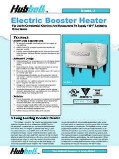
1 OPERATING AND MAINTENANCE . MANUAL FOR. electric booster HEATER. electric HEATER COMPANY. BASE MODEL J . UM ANSI/NSF5. 2017 Edition 1. HUBBELL. electric HEATER COMPANY. 45 SEYMOUR STREET. BOX 288. STRATFORD, CT 06615. PHONE: (203) 378-2659. FAX: (203) 378-3593. INTERNET: -- IMPORTANT -- Always reference the full model number and serial number when calling the factory. WARNING / CAUTION. 1. Tank is to be completely filled with water and all air is to be vented before energizing. 2. Due to the rigors of transportation, all connections should be checked for tightness before heater is placed in operation. 3. Safety relief valve must be installed in tapping provided. 4. The refractory material used in heating elements may absorb some moisture during transit, periods of storage, or when subjected to a humid environment. This moisture absorption results in a cold insulation resistance of less than one (1) megohms. If this heater has been subjected to the above condition, each heating element must be checked for insulation resistance before energizing.
2 Contact the factory for a replacement element. 5. KEEP AWAY FROM LIVE ELECTRICAL CIRCUITS. Do not perform any MAINTENANCE , make any adjustments, or replace any components inside the control panel with the high voltage power supply turned on. Under certain circumstances, dangerous potentials may exist even when the power supply is off. To avoid casualties, always turn the power supply safety switch to off, turn the charge or ground the circuit before performing any MAINTENANCE or adjustment procedure. 6. The unit is designed to operate at pressure not more than 150 psi. 7. Generalized instructions and procedures cannot anticipate all situations. For this reason, only qualified installers should perform the installations. A qualified installer is a person who has licensed training and a working knowledge of the applicable codes, tools, equipment, and methods necessary for safe installation of an electric resistance water heater. If questions regarding installation arise, check your local plumbing and electrical inspectors for proper procedures and codes.
3 If you cannot obtain the required information, contact the company. 8. Water Quality Requirements Recommended water hardness is 4 to 6 grains of hardness per gallon (GPG). Water hardness above 6 GPG should be treated by a water conditioner (water softener or in-line treatment). Water hardness below 4 GPG also requires treatment to reduce potential corrosion. Excessive GPG will result in higher OPERATING and MAINTENANCE costs and will reduce product longevity. Chlorides must not exceed 50 parts per million (ppm). Excessive chlorides will result in metallic corrosion and will reduce product longevity. Water treatment has been shown to reduce costs associated with de-liming the booster as well as reducing metallic corrosion. Product failure caused by these conditions is not covered under warranty. See warranty for complete details. 9. This water heater is not intended for space heating applications. 10. The water heater is factory set at 185 F for booster water heating applications.
4 This results in the possibility of a scalding water injury. A full thickness skin burn can occur in less than one second of exposure to water at this temperature. 2. TABLE OF CONTENTS. SECTION TITLE PAGE No. I GENERAL DESCRIPTION AND CONSTRUCTION 4. II INSTALLATION AND START-UP 9. III SCHEDULED MAINTENANCE AND OPERATION 24. IV TROUBLESHOOTING 26. V SERVICING AND REPLACEMENT OF PARTS 32. VI SERVICE PARTS LIST 35. VII TORQUE VALUES 37. VIII WARRANTY INFORMATION 38. 3. SECTION I - GENERAL DESCRIPTION AND CONSTRUCTION. GENERAL DESCRIPTION. This book describes a packaged electric booster heater that is typically used to provide 180 F. sanitizing rinse water. The complete assembly consists of the storage tank, immersion electric heating element(s), electronic control module, safety relief valve, magnetic contactor(s), and any other required electrical OPERATING control. Optional equipment may be supplied with your unit. Please consult the product packing list for details specific to your assembly.
5 The unit is factory assembled, insulated, jacketed, wired, tested, and ready for electrical and plumbing service connections. CAPACITY. Storage 40 F 70 F Storage 40 F 70 F. Model Capacity kW Rise Rise Model Capacity kW Rise Rise (gallons) (GPH) (GPH) (gallons) (GPH) (GPH). 3 30 17 J161 16 1 10 5. 3 58 33 16 15 8. 3 101 58 J162 16 2 20 11. 3 107 61 J163 16 3 30 17. 3 117 67 J164 16 4 41 23. J411 4 117 67 J166 16 6 62 35. J415 4 15 154 88 J167 16 7 72 41. J427 4 27 277 158 J169 16 9 92 53. J61 6 1 10 5 J1612 16 12 123 70. 6 15 8 J1613 16 138 79. J62 6 2 20 11 J1615 16 15 154 88. J63 6 3 30 17 J1618 16 18 185 105. J64 6 4 41 23 J1624 16 24 246 141. J65 6 5 51 29 J1627 16 27 277 158. J66 6 6 62 35 J1630 16 30 308 176. J67 6 7 72 41 J1636 16 36 369 211. J69 6 9 92 53 J1639 16 39 400 228. J610 6 108 62 J1640 16 415 237. J612 6 12 123 70 J1645 16 45 461 264. J613 6 138 79 J1654 16 54 554 316. J615 6 15 154 88 J1658 16 600 343. J618 6 18 185 105 J1664 16 64 656 375.
6 J624 6 24 246 141 J1666 16 66 677 387. J627 6 27 277 158 J1668 16 68 697 398. J630 6 30 308 176 J1679 16 79 810 463. J636 6 36 369 211 J1681 16 81 830 474. J639 6 39 400 228 J1685 16 85 871 498. J640 6 415 237 J1686 16 86 882 504. J645 6 45 461 264 J1688 16 88 902 515. J654 6 54 554 316 J1690 16 90 923 527. J658 6 600 343. 4. 5. 6. CONSTRUCTION. TANK. The storage tank is designed, manufactured, and stamped in accordance with ASME Section VIII, Division 1. The tank is constructed of type 304L stainless steel for maximum tank longevity and fabricated by all welded construction and is designed for a maximum allowable working pressure of 150 psi (225 psi test pressure). TANK CONNECTIONS. The heater is supplied with separate connections for the cold/warm inlet and the hot water outlet. Water entering the warm water inlet and leaving through the hot water outlet is evenly circulated by means of a diffuser within the tank. A -inch FNPT connection is provided for mounting a combination temperature and pressure safety relief valve.
7 An overflow line should be utilized from the relief valve outlet to a floor drain. See drawing for locations and sizes. HEATING ELEMENT. The water heater is supplied with an electric immersion heating element assembly(s), composed of corrosion resistant sheathed elements that are fitted into a 1 -12 UNF brass screw plug with a 1 hex. Each assembly is threaded into the tank and sealed with an o-ring gasket. See drawing for voltage and power ratings. Note that the J3 model element is a 1 NPS thread with a 1 . hex. MAGNETIC CONTACTOR. Load switching is done by a heavy-duty resistive (non-inductive). load type definite purpose magnetic contactor. The contactor supplies power to the heating element(s) when the relay on the control board is closed, thereby pulling in the contacts until the desired temperature is reached. At this point, the contacts will drop out, which in turn disconnects power from the elements. Units with multiple contactors will turn on and off in stages.
8 This contactor is good for 200,000 cycles. CONTROL BOARD AND DISPLAY. The control board supplies all the necessary functions for heater operation. These include control temperature, hi- limit cut-out, low water detection, and leak detection. LOW VOLTAGE CONTROL TRANSFORMER. A control circuit transformer is supplied with all models rated greater than 240-volts. This component is used to step down the primary power supply (600, 480, 440, 415, 380, or 277) to 208/240- volts for safety when working with control. POWER CIRCUIT BREAKERS. When required by code, a magnetic power circuit breaker is supplied for circuit overload protection. The circuit breaker can be reset in the event of a current overload. OUTER SHELL, INSULATION, AND SUPPORTS. The tank is encapsulated in high efficiency foam insulation meeting the requirements for UL 94. HF-1 rating. The protective shell is constructed of type 304 brushed stainless steel. NSF. approved adjustable plastic legs are provided for support.
9 Plastic legs for the J3 and J4 models are optional. DIAL TEMPERATURE AND PRESSURE GAUGE. A combination temperature (30 -240 F / 0 -120 C) and pressure (0 200 psi / 0-1400 kPa) gauge with 3-inch dial is supplied with the unit for in-line installation (shipped loose). The connection is NPT with a 2 long sensing probe. For the J3 and J4 models the gauges are optional. 7. PRESSURE REDUCING VALVE. A bronze pressure reducing valve with built-in bypass is supplied with the unit. This valve is shipped separately for in-line installation. The NPT valve is adjustable from 25-psi to 75-psi (approximately 17-psi to 67-psi including pressure drop through the valve). The inlet connection is supplied with a . union by sweat connection. The outlet connection is female NPT. The set screw located at the top of the diaphragm adjusts the pressure, turn clockwise to increase the pressure and counter-clockwise to decrease the pressure. Pressure reducing valves for the J3 and J4 models are optional.
10 DIELECTRIC UNIONS. Dielectric unions are provided for the inlet and outlet nipples to isolate stray ground currents to reduce the possibility of galvanic corrosion. (Optional on the J3 and J4 Models). OPTIONAL EQUIPMENT (not available on J4 Models). Slide Brackets Available for the J6 Model only, these brackets allow for mounting the booster heater under a counter. See slide bracket diagram on page 9 for details. Shock Absorber The optional shock absorber can be installed between the booster and the dishwasher to reduce the harmful pressures resulting from quick closing dishwasher solenoid valves. Legs In lieu of the standard black plastic legs, optional adjustable legs are available in stainless steel, die-cast nickel plated, and floor mount stainless steel. All optional legs are adjustable height type. Floor Mount Nickel Plated Stainless Steel Security Package For prison and other secure facilities a tamper resistant package is available. All external screws are spader type requiring a spader wrench for removal.