Transcription of Operating Instructions DULCOMETER D1C - …
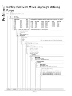
1 Operating InstructionsDULCOMETER D1 CPart 2: Adjustment and Operation,Measured Variable ChlorineProMinent D1C2-Cl-001-GBPart No. 987905 ProMinent Dosiertechnik GmbH 69123 Heidelberg Germany BA DM 173 03/09 GBPlease completely read through Operating Instructions ! Do not discard!The operator shall be liable for any damage causedby installation or Operating errors!Please enter the identity code of your device here!D1C A___ ___ ___ ___ ___ ___ ___ ___ ___ ___ ___ ___ WType , 12:10 Uhr121 Device Identification / Identity CodeD1C APlease enter the identity code of your device here!D1C ADULCOMETER Controller Series D1C / Version AType of mountingDControl panel installation 96 x 96 mm (IP 54)WWall mounting (IP 65) Operating voltage0230 V 50/60 Hz1115 V 50/60 Hz2200 V 50/60 Hz (only with control panel installation)3100 V 50/60 Hz (only with control panel installation)424 V AC/DCMeasured variableCChlorine ( ppm)
2 Connection of measured variable1 Terminal, standard signal 0/4-20 mACorrection variable0 None1pH for chlorine via standard signal 0/4-20 mAFeed forward control0 None1 Flow as standard signal 0/4-20 mA2 Flow as frequency 0-500 Hz3 Flow as frequency 0-10 HzControl input0 None1 PauseSignal output0 None1 Standard signal 0/4-20 mA measured value2 Standard signal 0/4-20 mA control variable3 Standard signal 0/4-20 mA correcting variable42 standard signal 0/4-20 mA outputs, freely programmablePower controlGAlarm and 2 limit value/timer relaysMAlarm and 2 solenoid valve relaysRAlarm relay and servomotor with feedbackPump control0 None2 Two pumpsControl characteristic0 None1 Proportional control2 PID controlLog , 12:10 Uhr232 General User InformationPage 1 Device Identification / Identity 2 2 General User 3 3 Device Overview / 4 4 Functional 5 5 Display 6 7 7 Restricted Operating 9 8 Complete Operating 15 9 Fault/ 29 General User InformationThese Operating Instructions describe the technical data and function of the DULCOMETER D1C controller,provide detailed safety information and are divided into clear Please observe the parts of these Operating Instructions applicable to your particularversion!
3 This is indicated in the Section Device Identification / Identity Code ! Correct measuring and dosing is only possible in the case of impeccable operation of thesensor. The sensor has to be calibrated / checked regularly!NOTEA form Documentation of controller settings type D1C is available for the purpose of documenting the , 12:10 Uhr34 DULCOMETER STOPSTARTG raphic display"Start/stop"Button"Enter"Button"U p"Button"Change"Button"Down"Button"Branc h back"ButtonDisplay fieldMeasured variableChlorineCHANGE buttonTo change over within a menu leveland to change from one variable toanother within a menu buttonStart/stop of control and buttonTo accept, confirm or save a dis-played value or status. For buttonTo increase a displayed numerical valueand to change variables (flashingdisplay)BRANCH BACK buttonBack to permanent display or to startof relevant setting buttonTo decrease a displayed numericalvalue and to change variables (flashingdisplay).
4 3 Device Overview / , 12:10 Uhr454 Functional DescriptionNOTEP lease refer to the description of the complete Operating menu in Section 8 for a detaileddescription of the individual characteristics of the DULCOMETER D1C controller! MenuThe D1C controller permits settings to be made in two different menus. All values are preset and can bechanged in the complete Operating controller is delivered with a restricted Operating menu so that the D1C controller can be usedeffectively in many applications from the very onset. If adaptations prove to be necessary, all relevantparameters can then be accessed by switching over to the complete Operating menu (see Generalsettings ). CodeAccess to the setting menu can be prevented by setting up an access code. The D1C controller is suppliedwith the access code 5000 which permits free access to the setting menu.
5 The calibration menu remainsfreely accessible even if access to the setting menu is blocked by the D1C can operate as a proportional controller or as a PID controller - dependent on the device version(see identity code) and the controlled variable is recalculated once a second. Control procedures which required rapid correctionof setpoint deviations (less than approx. 30 seconds) cannot be processed with this controller. The cycletimes must be taken into consideration when activating solenoid valves (pulse length) in the same way astheir running times when activating servomotors (3-point).Via the control input pause, the control function (selection of controlled variable) can be switched off. Thecalculation of the controlled variable starts again after cessation of pause . Forward ControlThe D1C controller can process a signal of a feed forward control. Depending on the device version (seeidentity code) and the setting, this signal can be obtained in any form of a 0 20 mA or 4 20 mA signal or asa digital contact signal with the maximum frequencies 10 Hz or 500 signal can be used, for example, for flow-proportional metering (multiplicative effect) or feed forward-dependent basic load metering (additive effect).
6 The result of control variable calculation from theproportional or PID control is multiplied by or added to the feed forward signal. A multiplicative feed forwardvariable at the level of the set rated value carries over the calculated control variable unchanged into thecontrol variable:Control variable = Feed forward variable/rated value x calculated control variableDuring start-up, the zero point has to be checked. The multiplicative feed forward control is not designedfor switching off permanently the actuating variable (signal 0).An additive feed forward variable at the level of the rated value results in maximum control variable:Control variable (max. 100 %) = Feed forward variable/rated value x max. control variable+ calculated control MessagesError messages and information are indicated in the bottom line in the permanent display 1. Errors to beacknowledged (acknowledgement switches off the alarm relay) are indicated by the.
7 Errors/noteswhich still apply after acknowledgement are indicated alternately. During correction variable processing(temperature for correction of pH-value), the value is indicated in the same line as the error/note. Faultswhich are rectified of their own accord due to changed Operating situations are removed from thepermanent display without the need for , 12:10 Uhr56 The display of the DULCOMETER D1C controller uses the following symbols:DescriptionCommentSymbolLimit value transgressionSymbolRelay 1, upperleftSymbolRelay 1, lowerleftSymbolRelay 2, upperrightSymbolRelay 2, lowerrightMetering pump 1 (chlorine)SymbolControl offleftSymbolControl onleftMetering pump 2 (dechlorine)SymbolControl offrightSymbolControl onrightSolenoid valve 1 (chlorine)SymbolControl offleftSymbolControl onleftSolenoid valve 2 (dechlorine)SymbolControl offrightSymbolControl onrightServomotorControl, open relayControl, close relayWithout controlThickness of barPosition feedbackincreases from left to rightduring openingStop button pressedManual meteringFault5 Display , 12.
8 10 Uhr67D1C2-Cl-008-GBCHANGE from selection to selectionChange numbers orsettings of selectionVariables flashENTER and save setting,continue to next menuBRANCH back withoutsaving settingBRANCH back tostart of settingText 1 Text 2 Selection 1 Selection 2 Text 1 Text 2 Selection 1 Selection 2 Access code, correctParametersettingCalibration notesPermanentdisplay 1 Permanentdisplay 2 CalibrationmenuVariousAccess codeSetting menusD1C2-Cl-007-GBThe various menus are selected withthe CHANGE buttonThe menu is started withthe ENTER buttonBRANCH BACK to permanent displayor to relevant setting menuNOTEA ccess to the setting menus can be barred with the access code!The number and scope of setting menus is dependent on the device version!If the access code is selected correctly in a setting menu, then the following setting menus are alsoaccessible!If within a period of 10 minutes no button is pressed, the unit automatically branches back from thecalibrating menu or a setting menu to the permanent display , 12:10 Ccalibration pHprobe in buffer2 !
9 PHcalibration pHcalib. 2 activeplease wait ! pHcalibration pHbuffer1:buffer2:temp. pHOnly with correction variable pHcorrecting valuesetting ?correcting valuepHlimit ppmupperlimitssetting ?Control with dead zoneFor normal controlPID controlProportional ppmsetpoint 2 upperctrl. parameterTi =Td =xp =setpoint 1 lower10 %ctrl. parameterxp =10 %controlsettings ?Only with controlcontrolpositive chlorregulated value:negative dechlormanual dosingcontrolcurrent :30 %normal15 %regulated rangegeneral settinginformationident-code: D1 CAsoftware versionDxCxxxxxxxxxxD1C-A1 relayaccess c.:== Operating ppmcalibration pHzero p.:slope 25 mV/pHcontrolcurrent :30 %with dead zonecontrolcurrent :30 %manualSetting incompleteoperatingmenuororFor manual pHlimit ppmlowerPermanent display 1 Permanent display 2only with control(w = setpoint) Clcalibration ClDPD- fwd.:reg. val. ppmppm70 %59 %zero p.: mA/ppmPositive values of control variable:Negative values of control variable:calibration Clzero p.
10 : mA/ppmChlorineDechlorine(chlorine destruction)Only with correction variable Ccalibration pHzero p.:slope 25 mV/pHcalibration pHprobe in buffer1 ! pHcalibration pHcalib. 1 activeplease wait ! pHcalibration pHbuffer1:buffer2:temp. pHmanual0 s0 sNumber and scope of setting menusis dependent on the to setting menus canbe blocked with access Operating Menu / , 12:10 Uhr89D1C2-Cl-011-GBPermanent display 1 Permanent display 2only with control(w = setpoint) fwd.:reg. val. ppm70 %59 %Positive values of control variable: ChlorineNegative values of control variable: Dechlorine(chlorinedestruction)Calibrati on of the Chlorine sensorDuring the calibration, the D1C sets the controller outputs to 0 . Exception: If a base load or manualcontroller output was set, these are maintained during the calibration. The standard signal outputs mA(measured value or correction value) are frozen.