Transcription of Operating Instructions Flowphant T DTT31, DTT35
1 BA218R/09/ InstructionsFlowphant T dtt31 , DTT35 Flow SwitchDTT31, DTT352 Endress+HauserTable of contents1 Safety Instructions .. Designated use .. Installation, commissioning and operation .. Operational safety .. Return .. 32 Device identification .. Nameplate .. 43 Installation .. Incoming acceptance, storage .. Dimensions .. 54 Wiring .. DC voltage version with M12 connector .. DC voltage version with valve connector .. 85 Operation .. Onsite operation .. 96 Maintenance ..177 Accessories .. Adapter concept for DTT35 .
2 Electrical connection .. Configuration kit .. 228 Troubleshooting.. Error messages and warning messages .. Repair .. Disposal .. Change status (release) .. Release history .. 249 Technical data .. Power supply .. Output .. Operating conditions .. 2510 Dangerous Goods sheet ..27 dtt31 , DTT35 Safety instructionsEndress+Hauser31 Safety Designated useThe Flowphant T is a flow switch for measurement and monitoring of mass flow rates in indus-trial processes. The device has been safely built with state-of-the-art technology and meets the applicable requirements and EC Directives.
3 It can, however, be a source of danger if used incor-rectly or for anything other than the designated Installation, commissioning and operationInstallation, electrical connection, commissioning, operation and maintenance of the measuring system must be carried out by trained, qualified specialists authorized to perform such work by the facility's owner-operator. The specialist must have read and understood these Operating Instructions and must follow the Instructions they contain. The device may only be modified and repair work carried out if this is explicitly permitted in the Operating Instructions .
4 Damaged devices which could be a source of danger may not be commissioned and must be labeled and identified as Operational safetyEx-areaThe Flowphant T is not approved for use in ReturnThe following procedures must be carried out before a device is returned to Endress+Hauser: Always enclose a fully completed Declaration of Contamination form with the device. Only then can Endress+Hauser transport and examine a returned device. A copy of the Declara-tion of Contamination can be found on the second last page of these Operating Instructions . Remove all fluid residues. This is particularly important if the fluid is hazardous to health, flammable, toxic, caustic, carcinogenic, etc.
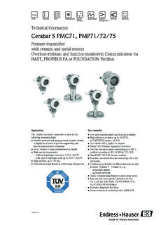
5 #Warning! Do not return a measuring device if you are not absolutely certain that all traces of hazardous substances have been removed, substances which have penetrated crevices or diffused through identificationDTT31, DTT354 Endress+Hauser2 Device NameplateTo identify your device, compare the complete order code and the version information on the delivery papers with the data on the 1: Nameplate for device identification (as example)!Note! The release number indicates the change status of the device. A change in the last two figures does not have any affect on the compatibility - see also Section coderConnection diagramnSerial numbersMeasuring rangeoTAG numbertAmbient temperature rangepRelease number (change status)uDegree of protectionqConnection valuesvApprovalsDTT31, DTT35 InstallationEndress+ Incoming acceptance, storage Incoming acceptance:Check the packaging and the device for damage.
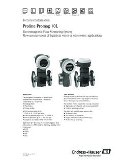
6 Check that the goods delivered are complete and nothing is missing. Storage:Storage temperature -40 C to +85 C (-40 F to 185 F). DimensionsA0005279 Fig. 2: Dimensions in mm (inch)Version L with 30 and 100 mm ( and in)M 12x1 connector as per IEC 60947-5-2M or " NPT valve plug as per DIN 43650A/ISO 4400 InstallationDTT31, DTT356 Endress+ Process connectionThe following table illustrates the versions of Flowphant of appli-cationMeasurement and monitoring of mass flow ratesMeasurement and moni-toring, mass flow rates in hygienic processesProcess con-nectionItem AVersion without process connec-tion ( w ).
7 Suit-able welding bosses and cou-pling (see section 7)Item BVersion with thread process connection ANSI " NPT(m = AF14) and " NPT(m = AF27)Item CVersion with thread process connectionG (n = AF14) and G (n = AF27)as per ISO 228 Item DAdapter concept - ver-sion with thread for adapters with process connection for hygienic processes (see section )Sensorlength LVersion L with 30 and 100 mm ( and in)Operational rangeLiquids from to m/s ( to ft/s) dtt31 , DTT35 InstallationEndress+ Installation instructionsMounting Instructions : Any orientation The onsite display can be rotated electronically 180 see section "Onsite operation" The housing can be rotated up to 310.
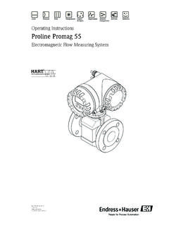
8 "Caution! Do not turn the device into the process connection thread at the housing. Always install the device at the hexagonal-headed bolt ( Fig. 3, item 1). Use a suitable open-ended wrench for this task (see Table Chap. ).!Note! For correct flow measurement, the complete sensor length must be immersed in the fully devel-oped flow 3: Installing the device (example). Sensor length L is completely immersed in the flow , DTT358 Endress+ DC voltage version with M12 4: Flowphant T with M12x1 connectorA1: 1x PNP switch outputA2: PNP switch outputs R1 and DC voltage version with valve connectorP01-PTx3xxxx-04-xx-xx-xx-003 Fig.
9 5: Flowphant T with M or " NPT valve plugB: 1x PNP switch outputDTT31, DTT35 OperationEndress+ Onsite operationThe Flowphant T is operated by means of three keys. The digital display and the light emitting diodes (LED) support navigation in the Operating 6: Position of Operating elements and possibilities for displayBackground illumination of the digital display: White = OK status Red = alarm/error statusOperationDTT31, DTT3510 Endress+ Navigating in the Operating menuT09-TTR31xxx-19-xx-xx-xx-002 Fig. 7: Navigating in the Operating menuA Function group selectionB Function selectionm Enter the Operating menu Press the E key for longer than 3 sn Select the "Function group" with the + or keyo Select the "Function" with the E keyp Enter or change parameters with the + or key Then return to "Function" with the E keyNote.
10 If software locking is enabled, it must be disabled before making entries or changesq Press the E key several times to return to the "Function group"r Jump back to the measuring position (Home position) Press the E key for longer than 3 ss Query to save data (select "YES" or "NO" with the + or key) Confirm with the E key!Note! Changes to the parameter settings only become effective if you choose s 'YES' when asked to save , DTT35 OperationEndress+Hauser11 Navigating the 'Learn' functiona0005785 Fig. 8: Navigating the 'Learn' function using the Calibration (CAL) function group as an examplem Select the HIF (Learn High Flow) or LOWF (Learn Low Flow) function with the E keyn Select the "RUN" function with the + key, learn function is initializedo Select the "WAIT" function with the + key, press for longer than 2 sp Accept ('learn') the current measured value after approx.