Transcription of Proline Promag 10L - shin-asystem.co.kr
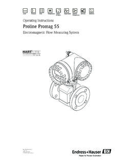
1 TI100D/06/ InformationProline Promag 10 LElectromagnetic Flow Measuring SystemFlow measurement of liquids in water or wastewater applicationsApplicationElectromagnetic flowmeter for bidirectional measurement of liquids with a minimum conductivity of 50 S/cm: Drinking water Wastewater Sewage sludge Flow measurement up to 2500 m /h (11 007 gal/min) Fluid temperature up to +90 C (+194 F) Process pressures up to 16 bar (232 psi) Lengths in accordance with DVGW/ISOA pplication-specific lining of the measuring pipe from polyurethane or PTFE with the following drinking water permissions: KTW WRAS NSF ACSYour benefitsPromag measuring devices offer you cost-effective flow measurement with a high degree of accuracy for a wide range of process uniform Proline transmitter concept comprises: High degree of reliability and measuring stability Uniform operating conceptThe tried-and-tested Promag sensors offer: No pressure loss Not sensitive to vibrations Simple installation and commissioning Flexible flange mountingProline Promag 10L2 Endress+HauserTable of contentsFunction and system design.
2 3 Measuring principle .. 3 Measuring system .. 3 Input .. 3 Measured variable .. 3 Measuring ranges .. 3 Operable flow range .. 3 Output .. 4 Output signal .. 4 Signal on alarm .. 4 Load .. 4 Low flow cutoff .. 4 Galvanic isolation .. 4 Power supply .. 4 Electrical connection, measuring unit .. 4 Electrical connection, terminal assignment .. 5 Electrical connection, remote version .. 5 Supply voltage (power supply) .. 5 Cable entry .. 5 Remote version cable specifications .. 6 Power consumption .. 6 Power supply failure .. 6 Potential equalization .. 7 Performance characteristics.. 8 Reference operating conditions .. 8 Maximum measured error .. 8 Repeatability .. 8 Operating conditions: Installations .. 9 Installation instructions .. 9 Inlet and outlet run .. 12 Adapters .. 13 Length of connecting cable .. 14 Operating conditions: Environment .. 15 Ambient temperature range.
3 15 Storage temperature .. 15 Degree of protection .. 15 Shock and vibration resistance .. 15 Electromagnetic compatibility (EMC) .. 15 Operating conditions: Process .. 16 Medium temperature range .. 16 Conductivity .. 16 Medium pressure range (nominal pressure) .. 16 Pressure tightness .. 16 Limiting flow .. 17 Pressure loss .. 17 Mechanical construction .. 18 Design, dimensions .. 18 Weight .. 23 Measuring tube specifications .. 24 Material .. 24 Material load diagram .. 24 Fitted electrodes .. 26 Process connections .. 26 Surface roughness .. 26 Human interface .. 26 Display elements .. 26 Operating elements .. 26 Remote operation .. 26 Certificates and approvals .. 26CE mark .. 26C-tick mark .. 26 Other standards and guidelines .. 26 Ordering information.. 27 Accessories .. 27 Documentation .. 27 Registered trademarks .. 27 Proline Promag 10 LEndress+Hauser3 Function and system designMeasuring principleFollowing Faraday's law of magnetic induction, a voltage is induced in a conductor moving through a magnetic the electromagnetic measuring principle, the flowing medium is the moving conductor.
4 The voltage induced is proportional to the flow velocity and is supplied to the amplifier by means of two measuring electrodes. The flow volume is calculated by means of the pipe cross-sectional area. The DC magnetic field is created through a switched direct current of alternating = B L vQ = A vUeInduced voltageB Magnetic induction (magnetic field)LElectrode spacingvFlow velocityQVolume flowAPipe cross-sectionICurrent strengthMeasuring systemThe measuring system consists of a transmitter and a versions are available: Compact version: Transmitter and sensor form a mechanical unit. Remote version: Sensor is mounted separate from the : Promag 10 (key operation, two-line, unilluminated display)Sensor: Promag L (DN 50 to 300 / 2 to 12")"Caution! To avoid corrosion, the sensor and process connection material must be selected considering the environmental and process variableFlow velocity (proportional to induced voltage)Measuring rangesMeasuring ranges for liquidsTypically v = to 10 m/s ( to 33 ft/s) with the specified accuracyOperable flow rangeOver 1000 : 1 UeIIBLVP roline Promag 10L4 Endress+HauserOutputOutput signalCurrent output Galvanically isolated Active: 4 to 20 mA, RL < 700 (for HART: RL 250 ) Full scale value adjustable Temperature coefficient: typ.
5 2 A/ C, resolution: APulse/status output Galvanically isolated Passive: 30 V DC / 250 mA Open collector Can be configured as: Pulse output: Pulse value and pulse polarity can be selected, max. pulse width adjustable (5 to 2000 ms), pulse frequency max. 100 Hz Status output: for example, can be configured for error messages, empty pipe detection, flow recognition, limit valueSignal on alarm Current output Failsafe mode can be selected ( in accordance with NAMUR Recommendation NE 43) Pulse output Failsafe mode can be selected Status output "Not conductive" in the event of fault or power supply failureLoad Section "output signal"Low flow cutoffSwitch-on points for low flow are isolationAll circuits for inputs, outputs and power supply are galvanically isolated from each supplyElectrical connection, measuring unitA0003192 Connecting the transmitter (aluminum field housing), cable cross-section max.
6 Mm2 (14 AWG)aElectronics compartment coverbPower supply cablecGround terminal for power supply cabledTerminal connector for power supply cableeSignal cablefGround terminal for signal cablegTerminal connector for signal cablehService connectoriGround terminal for potential equalizationbaeeb2127 25 26+24+L1(L+)N(L-)egbdhicfProline Promag 10 LEndress+Hauser5 Electrical connection, terminal assignmentElectrical connection, remote versionA0012461 Connecting the remote versionaWall-mount housing connection compartmentbSensor connection housing covercSignal cabledCoil current connected, insulated cable shieldsTerminal numbers and cable colors:5/6 = brown, 7/8 = white, 4 = green, 37/36 = yellowSupply voltage (power supply) 85 to 250 V AC, 45 to 65 Hz 20 to 28 V AC, 45 to 65 Hz 11 to 40 V DCCable entryPower supply and signal cables (inputs/ outputs): Cable entry M20 (8 to 12 mm / to ") Thread for cable entries, " NPT, G "Connecting cable for remote version: Cable entry M20 (8 to 12 mm / to ") Thread for cable entries, " NPT, G "Order versionTerminal (+)25 ( )26 (+)27 ( )1 (L1/L+)2 (N/L )10**-**APulse/status outputHART current outputPower supplyFunctional values 4, Section "Output signal" Section "Supply voltage" 416578437 36dcadcE1E2 GNDE5743742 Promag 10L6 Endress+HauserRemote version cable specificationsCoil cable 2 mm2 (18 AWG) PVC cable with common, braided copper shield ( 7 mm / ") Conductor resistance: 37 /km ( /ft) Capacitance core/core, shield grounded: 120 pF/m ( 37 pF/ft) Operating temperature: 20 to +80 C ( 68 to +176 F) Cable cross-section: max.
7 Mm2 (14 AWG) Test voltage for cable insulation: 1433 AC 50/60 Hz or 2026 V DCSignal cable 3 mm2 (20 AWG) PVC cable with common, braided copper shield ( 7 mm / ") and individual shielded cores With empty pipe detection (EPD): 4 mm2 (20 AWG) PVC cable with common, braided copper shield ( 7 mm / ") and individual shielded cores Conductor resistance: 50 /km ( /ft) Capacitance core/shield: 420 pF/m ( 128 pF/ft) Operating temperature: 20 to +80 C ( 68 to +176 F) Cable cross-section: max. mm2 (14 AWG)A0003194aSignal cablebCoil current cable1 Core2 Core insulation3 Core shield4 Core jacket5 Core reinforcement6 Cable shield7 Outer jacketOperation in zones of severe electrical interferenceThe measuring device complies with the general safety requirements in accordance with EN 61010 andthe EMC requirements of IEC/EN 61326."Caution! Grounding is by means of the ground terminals provided for the purpose inside the connection that the stripped and twisted lengths of cable shield to the ground terminal are as short as consumption 85 to 250 V AC: < 12 VA (incl.)
8 Sensor) 20 to 28 V AC: < 8 VA (incl. sensor) 11 to 40 V DC: < 6 W (incl. sensor)Switch-on current: Max. 16 A (< 5 ms) for 250 V AC Max. A (< 5 ms) for 28 V AC Max. A (< 5 ms) for 24 V DCPower supply failureLasting min. cycle frequency: EEPROM saves measuring system data1234567abProline Promag 10 LEndress+Hauser7 Potential equalization#Warning! The measuring system must be included in the potential measurement is only ensured when the fluid and the sensor have the same electrical potential. This is ensured by the reference electrode integrated in the sensor as following should also be taken into consideration for potential equalization: Internal grounding concepts in the company Operating conditions, such as the material/ grounding of the pipes (see table)Standard situationSpecial situationsOperating conditionsPotential equalization When using the measuring device in a: Metal, grounded pipePotential equalization takes place via the ground terminal of the transmitter.
9 !Note! When installing in metal pipes, we recommend you connect the ground terminal of the transmitter housing with the the ground terminal of the transmitterOperating conditionsPotential equalization When using the measuring device in a: Metal pipe that is not groundedThis connection method also applies in situations where: Customary potential equalization cannot be ensured. Excessively high equalizing currents can be sensor flanges are connected to the pipe flange by means of a ground cable (copper wire, at least 6 mm / in ) and grounded. Connect the transmitter or sensor connection housing, as applicable, to ground potential by means of the ground terminal provided for the ground cable is mounted directly on the conductive flange coating with the flange screws.!Note! The ground cable for flange-to-flange connections can be ordered separately as an accessory from Endress+ the ground terminal of the transmitter and the flanges of the pipeWhen using the measuring device in a: Plastic pipe Pipe with insulating liningThis connection method also applies in situations where: Customary potential equalization cannot be ensured.
10 Excessively high equalizing currents can be equalization takes place using additional ground disks, which are connected to the ground terminal via a ground cable (copper wire, at least 6 mm / in ). When installing the ground disks, please comply with the enclosed Installation the ground terminal of the transmitter and the optionally available ground disksProline Promag 10L8 Endress+HauserPerformance characteristicsReference operating conditionsAs per DIN EN 29104 and VDI/VDE 2641: Fluid temperature: +28 C 2 K (+82 F 2 K) Ambient temperature: +22 C 2 K (+72 F 2 K) Warm-up period: 30 minutesInstallation conditions: Inlet run > 10 DN Outlet run > 5 DN Sensor and transmitter grounded. The sensor is centered in the measured error Current output: also typically 5 A Pulse output: 2 mm/s ( in/s) ( = of reading)Fluctuations in the supply voltage do not have any effect within the specified measured error in % of readingRepeatabilityMax.