Transcription of Operating Instructions GENIUS Control Unit - …
1 Operating Instructions GENIUS Control unit 9 - 18812 96th Avenue Surrey, BC Canada, V4N 3R1. Tel: (001) 604 607-6028 Fax: (001) 604 607-6026. e-mail: 1 Customer Name: Location: Date in Service d/m/y: We would like to take this opportunity to thank you for purchasing your Metal Detector from TecTronix. The confidence you have placed in our product is sincerely appreciated and we will endeavour to provide the best service and support possible. Please take the time to read the User Manual completely as this provides you with the expertise necessary to install and adjust the system according to your requirements. In addition to this, you will learn about the sophisticated options provided by the GENIUS electronics.
2 If you have any problems in the set up and operation of your system, the TecTronix team are available to assist you. TecTronix Systems inc. 26688 56th Avenue Langley, British Columbia Canada, V4W 3X5. Telephone: (001) 604 607-6028. Fax: (001) 604 607-6026. E-mail: 2 Installation Do s and Don ts Electrical - Do Not cut the connector or the power cables These cables are equipped with special double shields and connectors and must not be cut. If you require longer or shorter cables please order them from our parts department. The electrical cables are approxi- mately 10 feet (3m) in length and the connector cables are 26 feet (8m). It is therefore recommended that consideration be given to where the connection boxes are located and that all cables be installed in conduit.
3 - Do Not weld in reasonable proximity to the metal detector Welding in the vicinity of the metal detector will trigger faults. - Run a clean, constant voltage power supply from the main to the Control panel Voltage fluctuations can cause false tripping therefore a constant voltage transformer is highly recom- mended. - Do Not install the metal detector near MCC's or Control panels Stray fields can trigger faults - Run the connector cables to the metal detector separately Connector cables are part of the metal detector and have to be protected against noise. It is highly recom- mended to run them in a dedicated conduit. Both cables can be run in the same conduit. The conduit should be metal but, must be grounded.
4 If the conduit is to be connected at the transmit/receive boxes on the coil and/or the Control panel, all fittings must be plastic. - Do Not install the detection coil inside an electromagnetic field (strong power supply fluctuations). Interferences can trigger faults. For example; Where units are installed in close proximity to chipper motors, when under high amperage draw, can cause nuisance or false tripping and this may require the fabrication of a shield. - Do Not disconnect the metal detector from the power supply main A constant, uninterrupted power supply enables more sensitive adjustments. Powering the unit on and off causes it to recalibrate during which time metal will not be detected. - When welding, do not use the Control panel mounting surface as a ground Mechanical - Do Not use conductive (Anti-Static) belt material Non-conductive belt material is preferred.
5 When splicing belts, use a "Finger over Finger" splice for best results. Ensure all surfaces are clean and free of debris at the splice. - Vibration less installation of the detector coil (except "VT"). Higher sensitivities can be attained and maintained if the Operating conditions are optimal. Ensure the coil is mounted to a structure that is stationery at all times. - Eliminate loose metal to metal connections near or within the detection field Intermittent metal to metal contacts from such things as roller axis, loose bolted connections, or broken welds can cause the metal detector to false trip especially on the higher sensitivity settings. - Vibration less installation of the Control Panel Mount the Control panel on a vibration free surface.
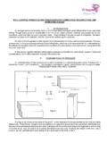
6 Vibration can cause premature electronic component failure. - Avoid cable whiplash . On "VT" Vibratory Conveyor installations, use the supplied cable clamps and tie wraps to secure the cables to the metal detector housing. Doing so will avoid whip lash at the transmit/receive box strain relief connec- tions. In addition to this we recommend that you loop the cables as they exit the conduit. These loops will then flex as the conveyor cycles. It is also advisable to follow this procedure on belt conveyor installations. - Do Not touch the sensor/coil surface of the detector Mechanical contacts may cause detection errors. Keep the sensing surface free of debris. - Mount the FLAT PLATE type coils as close as possible to the underside of the vibrating conveyor or belt conveyor The closer the coil to the product being conveyed, the greater the sensitivity.
7 Do not allow material to build up on the sensing face so that it touches the conveyor pan. Doing so creates a closed conductive loop and the metal detector will false trip. - Isolate rollers on belt and driven roll conveyors On belt and roller conveyor applications where a roller is less than 24" (610mm) from the centerline of the detector, the roller must be isolated on one side to avoid the possible effect of errant static charges. Use a UHMW shim beneath the bearing and nylon washers or some other non conductive material beneath the bolt head and nut/flat washer. The bolts should also be sleeved with a non conductive material. It may be neces- sary to isolate more than one roller in either direction to achieve the desired results.
8 3 Contents Contents 1 General information 6. Reasons for using the Control unit GENIUS 6. Symbols used 6. Legal basis 6. Overall view 6. 2 Technical data 7. Performance data 7. Dimensions 8. 3 Design and method of operation 9. Functional principle 9. Functional and Control elements 10. GENIUS - Housing 10. GENIUS - Controller board STE 11. GENIUS - Evaluation electronics board AWE 12. 4 Safety 13. Use to the intended purpose 13. Notification of risk 13. Risks in case of non-observance of the safety notes 13. Safety notes for the operator 13. Safety notes for operation and maintenance 13. Notes on residual risk 13. Consequences of unauthorized modification 13. Inadmissible operation 13. 5 Commissioning 14. Mechanical Mounting 14.
9 Connection of the equipment 14. Connector assignments on the controller board 14. Electrical connection 15. Electrical Performance 16. Electrical Connection of the equipment 17. 6 Operation / Menu structure 19. Quick start 19. Setting of the most important parameters 19. Teach-in procedure for new product 19. Operating mask and Adjustment menu 20. Set up menu 21. Check of detector adjustment and software version 21. Event recording by the GENIUS Log book 22. Activation of Access Codes 22. Time setting 22. Date setting 23. Language setting 23. Serial Interface configuration (option) 23. Setting of Device and Line name 23. Setting of the unit for conveying speed 24. Adjustment of the Air pressure monitor (option) 24.
10 Conveying speed setting with distance measurement (option belt conveyor) 24. Adjustment of Reject and Level monitor (option belt conveyor) 25. Adjustment of the Diverter position monitor (option pipe conveyor) 25. Adjustment of the Diverter Controller (option pipe conveyor) 26. 4 Contents Product teach-in menu 27. Selection of a product memory 27. Product parameter setting 27. Conveying speed 28. Automatic product teach-in 29. Manual setting of product parameters 30. Options for product effect equalization 30. Input / change of product name 31. Setting of the outputs 31. Activation of performance validation and scheduled testing 34. Menu Product change 34. 7 The use of the GENIUS metal detector for quality insurance 35.