Transcription of Operation Manual
1 WiringConnectionConnections should only be made with the powersupply turned separate routes for the pressure switch wiring andany power or high voltage wiring. Otherwise, malfunctionmay result due to that the FG terminal is connected to ground whenusing a commercially available switch-mode powersupply. When a switch-mode power supply is connected to the product,switching noise will be superimposed and the product specification can nolonger be met. This can be prevented by inserting a noise filter, such as aline noise filter and ferrite core, between the switch-mode power supply andthe product, or by using a series power supply instead of the switch-modepower ON and OFF point of the pressure (Hysteresis mode)When the pressure exceeds the set value, thePressure switch will turn the pressure falls below the setvalue by the amount of hysteresis ormore, the pressure switch will turn default setting of the output set valueis the central value between theatmospheric pressure and theupper limit of the rated pressurerange.
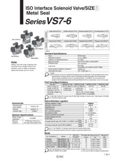
2 If this condition, shown to the right,is acceptable, then keep these SettingDigital pressure SwitchOperation ManualZSE80(F)/ISE80(H)Thank you for purchasing an SMC ZSE80(F)/ISE80(H) Series Digital read this Manual carefully before operating the product and make sure youunderstand its capabilities and keep this Manual handy for future obtain more detailed information about operating this product, pleaserefer to the SMC website (URL ) or contact InstructionsThese safety instructions are intended to prevent hazardous situations and/orequipment instructions indicate the level of potential hazard with the labels of"Caution", "Warning" or "Danger". They are all important notes for safety and mustbe followed in addition to International standards (ISO/IEC) and other LED (orange): Displays the switch display: Displays the current status of pressure , setting mode, selectedindication unit and error display modes can be selected: display always in red orgreen, or display changing from green to red, or red to green,according to the output (UP): Selects the mode or increases ON/OFF set this button to change to the peak display (DOWN): Selects the mode or decreases ON/OFF set this button to change to the bottom display (SET).
3 Press this button to change to another mode and to set a of Product partsInstallationMountingMount the optional bracket and panel mount adapter to the pressure the pressure switch is to be mounted in a place where water and dustsplashes occur, insert a tube ( 4, ) into the air-relieving port ofthe pressure and InstallationNames of individual partsLCD displayIndication LEDbutton (DOWN)button (UP)button (SET)CAUTION indicates a hazard with a low level of riskwhich, if not avoided, could result in minor ormoderate Operation Manual is intended for those who have knowledge of machineryusing pneumatic equipment, and have sufficient knowledge of assembly, Operation and maintenance of such equipment. Only those persons areallowed to perform assembly, Operation and and understand this Operation Manual carefully before assembling,operating or providing maintenance to the :Warning:Danger:WARNING indicates a hazard with a medium level ofrisk which, if not avoided, could result in death orserious indicates a hazard with a high level of riskwhich, if not avoided, will result in death or InstructionsDo not disassemble, modify (including changing the printed circuit board) or injury or failure can not operate in an atmosphere containing flammable or explosive or an explosion can product is not designed to be explosion not use the product in a place where static electricity is a it can cause failure or malfunction of the The direct current power supply to be used should be UL approved as follows:Circuit (of Class2) which is of maximum 30 Vrms ( V peak), with UL1310 Class2 power supply unit or UL1585 Class2 transformer.
4 The product is a approved product only if it has a mark on the using the product in an interlocking circuit: Provide a double interlocking system, for example a mechanical system Check the product regularly for proper operationOtherwise malfunction can result, causing an following instructions must be followed during maintenance: Turn off the power supply Stop the air supply, exhaust the residual pressure and verify that the air is released before performingmaintenance workOtherwise an injury can maintenance is complete, perform appropriate functional inspections and leak Operation if the equipment does not function properly or there is a leakage of leakage occurs from parts other than the piping, the product might be the power supply and stop the fluid not apply fluid under leaking cannot be assured in the case of unexpected not touch the terminals and connectors while the power is electric shock, malfunction or damage to the product can not operate the product outside of the not use for flammable or harmful , malfunction, or damage to the product can the specifications before SettingsPeak / Bottom hold displayZero clearKey lockTo set each of these functions, refer to the SMC website(URL )
5 For more detailed information, or contact to reset the product after a power cut or forcible de-energizingThe setting of the product will be retained as it was before a power cut output condition is also basically recovered to that before a power cut orde-energizing, but may change depending on the operating , check the safety of the whole installation before operating the product. Ifthe installation is using accurate control, wait until the product has warmed up(approximately 10 to 15 minutes).TroubleshootingError IndicationThis function is to display error location and content when a problem or an error with Dimensions (in mm)If the error can not be reset after the above measures are taken, then pleasecontact : Specifications are subject to change without prior notice and any obligation on the part of the manufacturer. 2011 SMC Corporation All Rights ReservedAkihabara UDX 15F, 4-14-1, Sotokanda, Chiyoda-ku, Tokyo 101-0021, JAPANP hone: +81 3-5207-8249 Fax: +81 3-5298-5362 URL with bracketFix the bracket to the pressure switch with the set screws M3 x 5 L (2 pcs.)
6 A tightening torque of Nm or less. Rear piping ..Bracket A (Model: ZS-24-A)Bracket D (Model: ZS-24-D) Bottom piping ..Bracket B (Model: ZS-35-A)M3 x 5 LBracket A or D<Rear piping>M3 x 5 LBracket B<Bottom piping>Measurement modeThe measurement mode is the condition wherethe pressure is detected and indicated, and theswitch function is is the basic mode, and the other modesshould be selected for setting changes and otherfunction mode1 s1 s1 sDisplay to show the unit specificationDisplay to show the productThe power is supplied1 sDisplay to show the standard productDisplay to show the pressure range2. [P_1] or [n_1] and set value aredisplayed in turn.<How to operate> : The pressure switch will also output during Press the button once in measurement in turnNormal outputReversed outputSwitch ONAt normal outputSwitch OFFSet valueP_1 Time [s] pressure [Pa]HysteresisH_13. Press the or button to change the set button is to increase and the button is to the button once to increase by onedigit, and press it continuously to keepincreasing the set the button once to decrease by onedigit, and press it continuously to keepdecreasing the set pressure switch operates within a set pressure range (from P1L to P1H)during window comparator mode.
7 Set P1L (switch lower limit) and P1H (switchupper limit) with the setting procedure above. (When reversed output isselected, [n1L] and [n1H] are displayed.)Zero clear of displayThe display is reset to zero when the and buttons are pressedsimultaneously for 1 the initial Operation , always perform zero clear with no pressure Press the button to complete the models with 2 outputs, [P_2] or [n_2] will be displayed. Set as above. : If the button is pressed for 2 seconds or longer, the setting is fixed and measurementmode SettingFunction selection modeIn measurement mode, press the buttonfor 2 seconds or longer to display [F 0].Select to display the function to be changed,[F]. Press the button for 2 seconds orlonger in function selection mode to returnto measurement mode. : Some functions are not available depending on partnumber. All functions are displayed with [F] followed by the function description. If a functionis not available, the function is displayed as [---].
8 Default settingAt the time of shipment, the following settings are the setting is acceptable, keep it for to the SMC website (URL ) for more detailedinformation about setting changes, or contact SMC.[F 0] Unit conversion functionUnit specificationModelNil or MISE80(H)ZSE80(F)Default settingPISE80(H)MPakPaZSE80(F)psiMeasure ment modeFunction selection modeFunction settingPress the button for2 s or specificationModelDefault setting[F 1] Setting of OUT1[F 2] Setting of OUT2 Same setting as [F 1] display colour is linked to the setting of OUT1, and can not be set parameter settingItemDefault setting[F 3] Setting of response ms[F 5] Setting of display resolution1000-split[F 7] Setting of fine adjustment of display value0% Manual [F 8] Setting of auto-presetOFF[F 9] Setting of power saving modeOFF[F10] Setting of security codeOFF[F98] Setting of all functionsOFF[F99] Reset to the default settingItemDescriptionOutput modeSelects hysteresis mode or window comparator outputSelects reversed settingSets ON or OFF point of the switch settingHysteresisChattering can be prevented by setting modeISE80: MPaZSE80: kPaZSE80F: kPaISE80H: MPaNormal outputISE80.
9 MPaZSE80: kPaZSE80F: kPaISE80H: MPaDisplay colourSelects the display : Green / OFF: Red[F 4] Setting of analogue output / auto-shift inputAnalogue outputThe switch output load current is more than80 the power off and remove thecause of the over current. Then turnthe power currenterrorError nameError displayError typeTroubleshooting methodResidualPressureerrorPressurizinge rrorSystemerrorDuring the zero clear Operation , pressureabove 10% of the span betweenatmospheric pressure and the upper limitof rated pressure has been applied. After 1second, the mode will return tomeasurement mode. The zero clear rangecan vary 1 digit with individual zero clear Operation againafter restoring the applied pressureto an atmospheric has exceeded the upper limit ofthe set pressure in the case of an internal applied pressure to a levelwithin the set pressure the power off and turn it resetting fails, an investigation bySMC Corporation will be has exceeded the lower limit ofthe set pressure measured pressure at auto-shift inputexceeded the set pressure range.
10 : After 1 s, measurement mode input signal is the connected equipmentand correct the (+)Analogue output /Auto-shift inputOUT1 OUT2 WhiteBlueDC(-)Refer to the product catalogue or SMC website (URL ) formore information about the product specifications and outline with panel mount adapter Panel mount adapter (Panel mount adapter A, B and mounting bracket included)Rear piping ..Model: ZS-35-CBottom piping ..Model: ZS-35-B Panel mount adapter + Front protective coverRear piping ..Model: ZS-35-FBottom piping ..Model: ZS-35-E<Rear piping> <Bottom piping>PanelFront protective cover(Option)Panel mountadapter APanel mountadapter BPanel mountadapter APanel mountadapter BPanelFront protective cover(Option)Mounting bracketMountingbracketPipingConnection using screw type fittingConnect suitable piping to the connect the hexagon socket head plug or fitting tothe pressure port, hold the hexagon part of thepressure port with a suitable spanner. Apply atightening torque of Nm or (17 mm)Tube attachmentWhen the pressure switch is used in a place where water and dust splashesmay occur, insert a tube into the air-relieving port and route the other end ofthe tube to a safe place away from water and dust.