Transcription of OPERATION MANUAL - SMC ETech
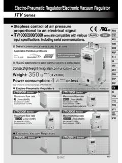
1 1 E/P REGULATORE/P REGULATORE/P REGULATORE/P REGULATOR MODEL NAMEMODEL NAMEMODEL NAMEMODEL NAME ITV1000, ITV2000, ITV3000 seriesITV1000, ITV2000, ITV3000 seriesITV1000, ITV2000, ITV3000 seriesITV1000, ITV2000, ITV3000 series SeriesSeriesSeriesSeries Contents P1 Safety instructions P2 Handling precautions P3-4 Wiring method P5-6 Setting method P7 Key locking function P8 Setting of min. pressure, max. pressure and switch output P9 Mode of switch output P10 Setting of preset pressure P11 Reset function P11 Error indicating function P12 Detail setting mode P13 Gain setting P13-14 Sensitivity setting P14 Zero clear P15 Initialize P15-16 LED display P16 URL OPERATION MANUAL CONTENTSCONTENTSCONTENTSCONTENTS 2 These safety instructions are intended to prevent a hazardous situation and/or equipment damage.
2 These instructions indicate the level of potential hazard by labels of CAUTIONCAUTIONCAUTIONCAUTION WARNINGWARNINGWARNINGWARNING , or DANGERDANGERDANGERDANGER . To ensure safety, be sure to observe ISO 4414, JIS B 8370 and other safety practices. Explanation of label LabelLabelLabelLabel Meaning of labelMeaning of labelMeaning of labelMeaning of label WARNINGWARNINGWARNINGWARNING Operator error could result in serious injury or loss of life. CAUTIONCAUTIONCAUTIONCAUTION Operator error could result in injury or equipment damage. WARNINGWARNINGWARNINGWARNING The compThe compThe compThe compatibility of pneumatic equipment is the responsibility of the person atibility of pneumatic equipment is the responsibility of the person atibility of pneumatic equipment is the responsibility of the person atibility of pneumatic equipment is the responsibility of the person who who who who designsdesignsdesignsdesigns the pneumatic system or decides its specifications.
3 The pneumatic system or decides its specifications. the pneumatic system or decides its specifications. the pneumatic system or decides its specifications. Since the products specified here are used in various operating conditions, their compatibility for the specific pneumatic system must be based on specifications or after analyses and/or tests to meet your specific requirements. The expected performance and safety assurance will be the responsibility of the person who has determined the compatibility of the system. This person should continuously review the suitability of all items specified, referring to the latest catalog information with a view to giving due consideration to any possibility of equipment failure when configuring a system.
4 Only trained personnel should operatOnly trained personnel should operatOnly trained personnel should operatOnly trained personnel should operate pneumatically operated machinery and e pneumatically operated machinery and e pneumatically operated machinery and e pneumatically operated machinery and Compressed air can be dangerous if an operator is unfamiliar with it. Assembly, handling or repair of pneumatic systems should be performed by trained and experienced operators. Do not service machinery / Do not service machinery / Do not service machinery / Do not service machinery / equipment or attempt to remove components until equipment or attempt to remove components until equipment or attempt to remove components until equipment or attempt to remove components until safety is is is is confirmed.
5 A. Inspection and maintenance of machinery / equipment should only be performed once safety of personnel and equipment is confirmed. B. When equipment is to be removed. Stop supplied air, exhaust the residual pressure, verify the release of air, turn the power off and confirm safety before performing maintenance. C. Before machinery / equipment is restarted, ensure safety before applying power. Contact SMC if the product is to be used in any of the following SMC if the product is to be used in any of the following SMC if the product is to be used in any of the following SMC if the product is to be used in any of the following conditions. A. Conditions and environments beyond the given specifications, or if product is used outdoors.
6 B. Installation on equipment in conjunction with atomic energy, railway, air navigation, vehicles, medical equipment, food and beverages, recreation equipment, emergency stop circuits, clutch and brake circuit in press applications, or safety equipment. C. An application which has the possibility of having negative effects on people, property, or animals requiring special safety analysis. Safety instructionsSafety instructionsSafety instructionsSafety instructions 3 CAUTIONCAUTIONCAUTIONCAUTION If power to this product is cut off due to a power failure, etc. when it is in a controlled state, residual pressure will be retained temporarily. Handle carefully when operating with output pressure released to the atmosphere, as air will continue to flow out.
7 If supply pressure to this product is interrupted or shut off, while the power is still on, the internal solenoid valve will continue to operate and a humming noise may be generated. Since the life of the product may be shortened, shut off the power supply also when supply pressure is interrupted or shut off. The optional cable connector is a 4 wire type. When the monitor output (analogue output or switch output) is not being used, prevent it from touching the other wires as a malfunction could occur. This product is adjusted for each specification at the time of shipment from the factory. Avoid careless disassembly or removal of parts, as this can lead to malfunction.
8 Handling precautionsHandling precautionsHandling precautionsHandling precautions 4 CAUTIONCAUTIONCAUTIONCAUTION Take the following steps to avoid malfunction due to noise. 1) Install a line filter etc. to the AC power line to reduce / eliminate power supply noise. 2) Avoid malfunction due to noise by installing this product and its wiring away from strong electric fields, such as those of motors and power line, etc. 3) Be sure to implement protective measures against load surge for induction loads (solenoid valves, relays etc.). 4) Turn off the power supply before installing or removing the connector. Please note that the right angled cable connector does not rotate and is limited to only one entry direction.
9 5 CAUTIONCAUTIONCAUTIONCAUTION Proceed carefully, as incorrect wiring can cause damage. Use DC power supply with sufficient capacity and a low ripple. Turn off the power supply to remove and insert the connector. Never turn the right angled type connector as it is not designed to turn. Note) The wire color is for when optional cable is used. Wiring Wiring Wiring Wiring diagram (diagram (diagram (diagram (Power supply and input signal)Power supply and input signal)Power supply and input signal)Power supply and input signal) Current/Voltage type ITV 0 -0 ITV 0 -1 ITV 0 -2 ITV 0 -3 Power supply 24 VDC ITV 0 0- 12 15 VDC ITV 0 1- Input signal 4 20mADC ITV 0 -0 0 20mADC ITV 0 -1 0 5 VDC ITV 0 -2 0 10 VDC ITV 0 -3 Preset input type ITV 0 -4 Power supply 24 VDC ITV 0 0-4 12 15 VDC ITV 0 1-4 Wiring methodWiring methodWiring methodWiring method Brown Power supply White Input signal Blue GND(COMMON)
10 Black Monitor output Power supply Input signal Brown Blue White Black + - + - Relation between preset pressure and switch Preset pressure P_1 P_2 P_3 P_4 S1 OFF ON OFF ON S2 OFF OFF ON ON Power supply Brown Blue White Black + - S1 S2 6 Wiring diagramWiring diagramWiring diagramWiring diagram Monitor outputMonitor outputMonitor outputMonitor output CAUTIONCAUTIONCAUTIONCAUTION When the monitor output is not being used, prevent it from touching the other wires as this can cause a malfunction. Analogue output Voltage type ITV 0 - 1 Analogue output Current (sink) type ITV 0 - 4 Only use equipment with a minimum load impedance of 100k.