Transcription of Operational Amplifiers and Negative Feedback
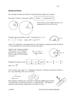
1 Physics 3330 Experiment #4 Fall 2013 Experiment #4 Operational Amplifiers and Negative Feedback Purpose This experiment shows how an Operational amplifier (op-amp) with Negative Feedback can be used to make an amplifier with many desirable properties, such as stable gain, high linearity, and low output impedance. You will build both non-inverting and inverting voltage Amplifiers using an LF356 op-amp. Introduction The purpose of an amplifier is to increase the voltage level of a signal while preserving as accurately as possible the original waveform. In the physical sciences, transducers are used to convert basic physical quantities into electric signals, as shown in Figure An amplifier is usually needed to raise the small transducer voltage to a useful level.
2 A small voltage or current change at the input of the amplifier controls a much larger signal at the input of whatever circuit or instrument the amplifier s output is connected to. Measuring and recording equipment typically requires input signals of 1 to 10 V. To meet such needs, a typical laboratory amplifier might have the following characteristics: 1. Predictable and stable gain. The magnitude of the gain is equal to the ratio of the output signal amplitude to the input signal amplitude. 2. Linear amplitude response, so that the output signal is directly proportional to the input signal.
3 Transducer Oscilloscope Data Analysis System amplifier Temperature, Magnetic Field, Radiation, Acceleration, etc. DC Power Volts to mVolts Figure Typical Laboratory Measurement Volts Experiment #4 3. According to the application, the frequency dependence of the gain might be a constant independent of frequency up to the highest frequency component in the input signal (wideband amplifier ), or a sharply tuned resonance response if a particular frequency must be picked out. 4. High input impedance and low output impedance are usually desirable. These characteristics minimize changes of gain when the amplifier is connected to the input transducer and to other instruments at the output.
4 5. Low noise is usually important. Every amplifier adds some random noise to the signals it processes, and this noise often limits the sensitivity of an experiment. We will learn about amplifier noise in Experiment 8. Commercial laboratory Amplifiers are readily available, but a general-purpose amplifier is expensive (>$1000), and most of its features might be unneeded in a given application. Often, it is preferable to design your own circuit using a cheap (<$1) op-amp chip. Op-amps have many other circuit applications. They can be used to make filters, limiters, rectifiers, oscillators, integrators, and other devices (see FC ).
5 To get an idea of the variety of op-amps available, have a look at the National Semiconductor web site ( ). They currently make over 300 types, offering trade-offs between speed, cost, power consumption, precision, etc. The op-amp is the most important building block of analog electronics. Suggested Readings 1. FC Sections The basic rules of op-amp behavior and the most important op-amp circuits. [Note while FC discussed basic characteristics of op amps in it does not have the I, II Golden Rule analysis that we will discuss in class.] Do not worry right now about the transistor guts of op-amps.
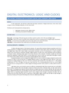
6 We will learn about transistors in Experiments 7-8. 2. Horowitz and Hill, Chapter 4. 3. The IC Op-Amp Cookbook, by Walter Jung, 3rd edition (Prentice Hall, 1997). 4. Diefenderfer Chapter 9 5. Bugg, Chapter 7, particularly Sections , , and Experiment #4 Theory The two basic op-amp circuit configurations are shown in Figs. and Both circuits use Negative Feedback , which means that a portion of the output signal is sent back to the Negative input of the op-amp. The op-amp itself has very high gain, but relatively poor gain stability and linearity. When Negative Feedback is used, the circuit gain is greatly reduced, but it becomes very stable, limited only by the temperature dependence of the resistors R and RF.
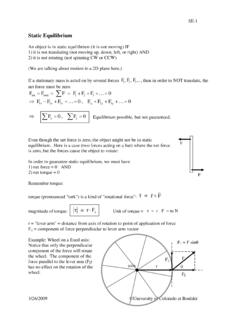
7 At the same time, linearity is improved and the output impedance decreases. Both configurations are widely used because they have different advantages. Besides the fact that the second circuit inverts the signal, the main differences are that the first circuit has a much higher input impedance, while the second has lower distortion because both inputs remain very close to ground. The gain or transfer function A of the op-amp alone is given by where the denominator is the difference between the voltages applied to the + and - inputs. We use the symbol G for the gain of the complete amplifier with Feedback : G Vout/Vin.
8 This gain depends on the resistor divider ratio B R/(R+RF). In Feedback amplifier lore A is called the open loop gain, G is called the closed loop gain, and the product A B is called the loop gain. You can see the reason for these names if you imagine opening the Feedback loop in Fig. by disconnecting the input. V out V out A Figure Inverting amplifier R R F Figure Non-inverting amplifier amplifier + V in R R F + V in A ininoutVVVAE xperiment #4 If we assume that A , that the op-amp input impedance is infinite, and that the output impedance is zero, then the behavior of these circuits can be understood using the simple Golden Rules : I.
9 The voltage difference between the inputs is zero. ( voltage rule ) II. No current flows into (or out of) each input. ( current rule ) The Golden Rule analysis is very important and is always the first step is designing op-amp circuits, so be sure you understand it before you read the material below, where we consider the effect of finite values of A, mainly so that the frequency dependence of the closed loop gain G can be understood. GAIN EQUATION NON-INVERTING CASE The basic formula for the gain of Feedback Amplifiers is derived in FC, Section From Fig. we can see that: outinoutBVVAV Solving this equation yields: ABAVVG inout 1 (1) With B=R/(R+RF) the above equation for the closed loop gain then gives which is the Golden Rule result.
10 If we don't care about corrections due to the finite value of A, then Equation (1) is not needed and the analysis can be done using just the Golden Rules. INPUT AND OUTPUT IMPEDANCE NON-INVERTING CASE Formulas for the input and output impedance are derived in H&H Section The results are where Ri and Ro are the input and output impedances of the op-amp alone, while the primed symbols refer to whole the amplifier with Feedback . These impedances will be improved from the values for the bare op-amp if the loop gain A B is large. R i Ri(1 AB) R o Ro/(1 AB)G 1 R f R if A 1 Experiment #4 FREQUENCY DEPENDENCE NON-INVERTING CASE The above formulas are still correct when A and/or B depend on frequency.