Transcription of Operational Amplifiers - Learn About Electronics
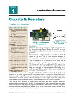
1 AAMPLIFIERS module 1 E. COATES 2007 -2012 Operational Amplifiers The Ideal Amplifier The Ideal Amplifier In amplifier modules 1 to 5 voltage and power Amplifiers are described in some detail so that the circuit elements that go into making an amplifier can be understood. Each of these circuit elements, such as negative and positive feedback, impedance, linearity, gain and efficiency are used with the aim of improving the amplifier s performance towards the goal of making the ideal amplifier.
2 The bad news is that the ideal amplifier does not exist, but the good news is that the op amp does! Amplifiers module 6 What you ll Learn in module 6. Section Introduction to Operational Amplifiers . Understand Concept of the Ideal Amplifier and the Need for Integrated Circuits. Section Op Amp Inputs. Typical op amp input requirements. Section Comparators. Open Loop Mode, The Schmitt Trigger. Hysteresis & Positive Feedback. Section Voltage Amplifiers . The ideal op amp, NFB, Op amp rules. Inverting & non-inverting Amplifiers .
3 Section Op Amp Characteristics. Power supplies, Open loop voltage gain. Large signal voltage gain, Gain bandwidth product. Input offset current , Maximum differential input. Input resistance, Temperature coefficient. Slew rate, Power bandwidth. Section Op Amp Packages. Op amp pin out examples. Section Op Amp Circuits. Voltage follower, Differential amplifier. Summing Amplifier, Differentiator. Integrator, Active filters. Section Op Amps Quiz. Test your knowledge & understanding of op amps. Amplifiers module 6 Amplifiers module 2 E.
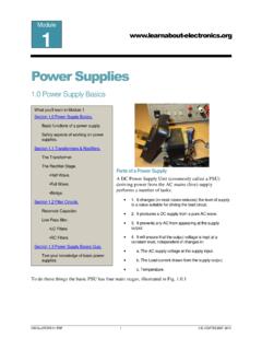
4 COATES 2007 -2012 The ideal amplifier should: Have an infinitely wide bandwidth. Have an infinitely high gain available that can be easily controlled. Be ideally linear, with no distortion. Generate no noise (have an infinitely high signal to noise ratio). Be easily convertible to perform different amplifier functions. Be cheap. All of the above is what the op-amp does, or at least comes pretty close to. Early Op amps Amplifiers with gain controlled by negative feedback were first thought of in the 1930s as a way of creating Amplifiers for the telephone system that could have a controllable and reliable gain, but became Operational Amplifiers when they were adopted by designers of analogue computers, because of their ability to perform accurate mathematical operations, such as adding, subtracting, integration and differentiation.
5 Op amp ICs Operational Amplifiers can still built from discrete components but with the introduction of silicon planar technologies and integrated circuits their performance improved and both size and cost reduced dramatically, and although computing has practically all moved from analogue circuitry to digital, the op amp had become so useful in so many circuits that deal with real (analogue) quantities such as sound, light, heat and motion, that the op amp is now a widely varied and indispensable part of Electronics equipment. This module will discuss the basic properties of op amps and comparators, and how their integrated circuit versions can be manipulated to make simple circuits that provide so many vital functions in Electronics .
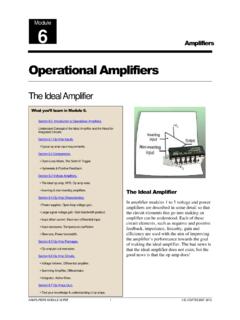
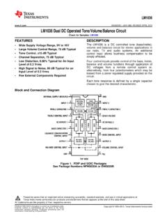
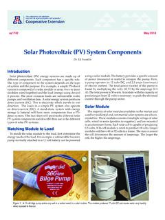
6 Amplifiers module 6 Amplifiers module 3 E. COATES 2007 -2012 module Op Amp Inputs Op Amp circuit Symbol The circuit symbol for an op amp is basically the standard triangle symbol for an amplifier. Main connections such as the inverting ( ) and non-inverting inputs and the output are shown, but often, other connections are not. A typical op amp symbol is shown in Fig. Note however, that many circuit diagrams do not show the DC supply connections.
7 Dual Power Supplies An op amp needs a minimum of five connections as shown in Fig ; as well as the two inputs and one output there are two power supply connections. These may be labelled +Vs and -Vs indicating that the IC needs both positive and negative supplies. These will often be in the range of +5V to +15V for the positive supply and -5V to -15V for the negative supply. This dual supply arrangement allows for the output voltage to swing both above and below zero volts, and also gives an output of 0V when there is no voltage difference between the two inputs.
8 Single Supply Op Amps A growing number of op amps are available however, that use a single supply, labelled +V and Gnd or 0V. This is a useful arrangement for many portable and mobile applications where dual positive and negative supplies are not readily available, for example in automobile applications. High Gain Negative Feedback DC Amplifier Op amps are basically negative feedback (NFB) DC Amplifiers . The op amp has a very large gain, the output can be hundreds of thousands times larger than the input. This huge gain however, is reduced using negative feedback to produce a circuit whose gain is stable and independent of the semiconductor characteristics.
9 Op amps are also always DC coupled, unlike an amplifier using discrete components where it is possible to include AC components such as capacitors and inductors, in a tiny integrated circuit it is not possible to fabricate AC components large enough to be useful at audio frequencies, therefore an op amp MUST be a DC amplifier. What you ll Learn in module After studying this section, you should be able to: Recognise typical forms of op amp circuit symbols. Understand the need for single & dual power supplies. Understand typical operating requirements.
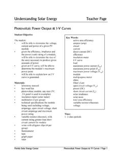
10 High gain & negative Feedback. Differential inputs. Constant current sourcing. Common Mode Rejection, CMRR. Offset null. Fig. Op Amp circuit Symbol Amplifiers module 6 Amplifiers module 4 E. COATES 2007 -2012 One advantage of using DC (directly coupled or direct current ) Amplifiers is that their bandwidth extends right down to 0Hz, making them suitable for many control and measurement applications where the op amp s ability to produce a DC output, relative to the difference between two DC input quantities is extremely valuable.