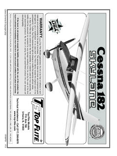
Transcription of Operator’s Manual - Hobbico
1 1 DLE-30 operator s cc [ cu. in.] / 8,500 rpm1,6 0 0 r pmElectronic Ignition 18u8, 18u10, 19u8, 20u8CM6(Gap) in. [ ] [ 36 mm] u in . [ 3 0 m m ]7. 6 : 1 DLE with Manual ChokeMain Engine 2 lb [ 910 g ] Muffler [60 g ] Electronic Ignition [120 g]Engine Mount Standoffs [20 g]87 93 Octane Gasoline with a 30:1gas/2- stroke (2- cycle) oil mixtureDisplacement:Performance:Idle Speed:Ignition Style:Recommended Propellers:Spark Plug Type:Diameter Stroke: Compression Ratio:Carburetor:Weight: Fuel: 2010 Hobbico , Mnl 2 Parts List (1) DLE-30cc Gas Engine with DLE carburetor(1) CM6 Spark plug with spare ignition wire spring(1) Muffl er w/gasket(2) 5x20mm SHCS (muffl er mounting)(1) Electronic Ignition Module w/ additional tachometer lead(4) 30mm Engine Mounting Standoffs(4) 4x30mm SHCS with 4mm lock washers & fl at washers (propeller mounting)(4) 5x25mm SHCS with 5mm fl at washers (mounting engine to standoffs)(1) Silicone Pick-up Wire Cover / Ignition Wire Cover(1) Red Three Pin Connector Lead w/ Pig Tail (ignition switch)(1) Long Heavy Duty Throttle Control Arm(2) Three Pin Connector Securing Clips(1)
2 DLE Decal SetSafety Tips and Warnings This engine is not a toy. Please place your safety and the safety of others paramount while operating. DLE will not be held responsible for any safety issues or accidents involving this engine. Operate the engine in a properly ventilated area. Before starting the engine, please make sure all components including the propeller and the engine mount are secure and tight. It is strongly recommended that a screw sealant is used (Great Planes Threadlocker GPMR6060) during engine installation. During the break-in period, it is recommended that the engine be installed on the aircraft or a test stand with an appropriate shock absorber.
3 Otherwise it is probable that vibration could rebound 3back to the engine and serious damages may occur during the break-in period. For your safety and the safety of others, please do not stand in front or in line with the propeller when the engine is running. Keep onlookers away from the running engine, especially small children. Always use a balanced spinner and a balanced propeller. An unbalanced spinner and propeller combination will cause high levels of vibration and may cause the propeller shaft to break. Always use a lightweight spinner on your engine. Lightweight spinners are considered to be those with a cone wall of 1mm or less. Heavy spinners could cause the propeller shaft to break.
4 Securely tighten the spinner and propeller on the engine to prevent them from being thrown off the engine while running. Never use a propeller that has hit the ground. Even though it may look good from the outside, it may be cracked on the inside which may cause it to disintegrate while in use. Do not use a nicked, cracked or split propeller. Keep foreign objects away from the propeller. Make sure that nothing can be sucked in by the propeller. Never start the engine on loose gravel or sand. Do not attempt to stop the engine by throwing anything into the path of the propeller. Make sure the fuel line is well-secured to the engine and to the fuel tank so that it won t come off in fl ight.
5 Do not use silicone fuel line because it will be dissolved by the fuel. Use gasoline approved rubber fuel line. Always secure the fuel line away from the cylinder head. The engine s heat can damage the fuel line. Never touch the engine immediately after a run. The engine will be hot. Before transporting your model, remove all the fuel from the fuel tank and fuel lines. Always use high-quality oil intended for 2-stroke (2-cycle) 's a good idea to use a petroleum-based 2-cycle motor oil like Lawn Boy All Season - Ashless, Generation II oil for the break-in period. Break-in should be considered about the fi rst 3-5 gallons you run in the engine.
6 A high quality synthetic 2-cycle oil is recommended for optimum performance and a longer engine life. Synthetic 2-cycle oils leave fewer combustion byproducts than natural oil which can foul the engine and exhaust ports, resulting in reduced performance. Synthetic oils also better reduce friction and provide more fl uidity at low The throttle and choke pushrods should be non-metallic. If the engine is not to be used for more than a month, drain the fuel tank and remove any fuel from inside the carburetor. Do this by running the engine at idle until it quits by running out of fuel. Keeping gasoline inside the carburetor over an extended period of time will damage the diaphragm valve and clog passages inside the carburetor.
7 Due to the carburetor being more complicated than those used in glow engines, keep the fuel clean by using a fuel fi lter. Use a fi lter intended to be used with gasoline engines. Metal fi lters intended for glow engine are too coarse and will not screen out fi ner particles. Always fi lter your fuel by using an appropriate fi lter before putting it into the airplane s fuel tank. Gasoline is extremely fl ammable. Keep it away from an open fl ame, excessive heat or sources of sparks. Do not smoke near the engine or the fuel tank. This engine was designed for use in a model aircraft. Do not attempt to use it for any other purpose. Always install an ignition system kill switch on the aircraft used.
8 Do not install your throttle servo or kill switch servo inside the engine compartment. Doing so could cause radio interference. Install all electronic radio devices at least 12 [305mm] away from the engine. Caution: Running the engine with a lean gas mixing will cause the engine to overheat and burn the electrode of the spark plug. Pay close attention to the High-speed Needle adjustment. Running the engine with the proper gas mixing will cause the spark plugs to appear yellow at the ignition point. For optimum performance please use fresh or recently purchased 93 octane gasoline (87 octane gasoline will suffi ce) with a 30:1 gas/oil Mixing Chart1 Gallon Gasoline (128 fl ) / 2-Cycle Oil ( ) = 30:1 ratio Excessive running of the engine at idle speed can result in a seriously carbonized spark plug.
9 Keep the surface of the engine clean to ensure proper heat dissipation. Ensure proper cooling/ventilation around the cylinder with adequate air exhaust. To avoid permanent damage to the electronic ignition system, NEVER rotate the propeller on your DLE engine with the electronic ignition system switched on and the plug not installed in the plug InstructionsPrepare the engine for installation1. Check to see that all screws and bolts are tight. Check carefully for any cracks, broken or missing parts. Tighten or replace any damaged or missing parts before proceeding. 2. Install the silicone wire cover over the pick up lead coming from the engine (cut the excess silicon wire cover) and connect the lead to the pick up lead from the Electronic Ignition Module.
10 Secure the connection with the included three pin connector securing clip. 3. Connect the kill switch lead to the red connector from the ignition control module using the lead from the kill switch or with the included 6three pin connector with pig tail. Use one of the included three pin securing clips to secure the Connect the ignition module battery to the kill switch. Any , 1000mAh and above capacity battery will work well for this. Use heat shrink tubing to secure this Install the ignition kill switch on the aircraft so that it is easily accessible through the cowling or the Install the ignition module and battery securely in the airplane forward area.