Transcription of Optical Transport Network (OTN) Tutorial
1 Contact: Timothy P. Walker AMCC USA Tel: 1-978-247-8407 Fax: Email: Optical Transport Network (OTN) Tutorial Disclaimer: This is a Tutorial . This is NOT a Recommendation! This Tutorial has no standards significance. It is purely for educational purposes. In case of conflict between the material contained in the Tutorial and the material of the relevant Recommendation the latter always prevails. This Tutorial should NOT be used as a reference; only the relevant Recommendations can be referenced. Summary This document provides a Tutorial for Optical Transport Network standards and their applications. The objective is to provide the telecommunications engineers with a document that forms the basis for understanding OTN. - 2 - 1 2 3 What is OTN 4 Where is it standardized 5 Why use Forward Error Correction (FEC)..8 Theoretical Coding Tandem Connection Transparent Transport of Client Switching 6 OTN Hierarchy 7 OTUk, ODUk, OPUk Frame 8 OPUk Overhead and OPUk Overhead Byte Payload Structure Identifier (PSI).
2 22 Payload Type (PT)..22 Mapping Signals into an Frequency Mapping a CBR2G5 signal ( STM-16) into Mapping a CBR10G signal ( STM-64) into Mapping a CBR40G signal ( STM-256) into 9 ODUk Overhead and Path Monitoring (PM) Byte Trail Trace Identifier (TTI)..29 Backward Defect Indication (BDI)..29 Backward Error Indication and Backward Incoming Alignment Error (BEI/BIAE)..30 Path Monitoring Status (STAT)..30 Tandem Connection Monitoring (TCM)..30 Trail Trace Identifier (TTI)..30 Backward Defect Indication (BDI)..31 - 3 - Backward Error Indication and Backward Incoming Alignment Error (BEI/BIAE)..31 TCM Monitoring Status (STAT)..32 Tandem Connection Monitoring ACTivation/deactivation (TCM-ACT)..33 General Communication Channels (GCC1, GCC2)..33 Automatic Protection Switching and Protection Communication Channel (APS/PCC)..33 Fault Type and Fault Location reporting communication channel (FTFL).
3 33 10 OTUk Overhead and Frame Alignment Frame alignment signal (FAS)..35 Multiframe alignment signal (MFAS)..35 SM Byte Trail Trace Identifier (TTI)..37 Backward Defect Indication (BDI)..38 Backward Error Indication and Backward Incoming Alignment Error (BEI/BIAE)..38 Incoming Alignment Error (IAE)..39 General Communication Channel 0 (GCC0)..39 11 ODUk Multiplexing Data ODU1 to ODU2 Justification ODU2 to ODU3 Justification ODU1 to ODU3 Justification 4 x ODU1 to ODU2 4 x ODU1 to ODU2 Multiplexing 4 x ODU1 to ODU2 Justification OPU2 Payload Structure Identifier (PSI)..44 OPU2 Multiplex Structure Identifier (MSI)..44 Frequency ODU1/ODU2 to ODU3 ODU1/ODU2 to ODU3 Multiplexing ODU1/ODU2 to ODU3 Justification OPU3 Payload Structure Identifier (PSI)..49 OPU3 Multiplex Structure Identifier (MSI)..49 Frequency Maintenance Signal - 4 - Client source Client source Line source Defect detection and dPLM (Payload Mismatch).
4 52 dMSIM (Multiplex Structure Identifier Mismatch supervision)..53 dLOFLOM (Loss of Frame and Multiframe)..53 aAIS (AIS insertion)..54 SSF (Server Signal Fail)..54 12 ODUk Virtual Concatenation / OTN over 13 Network Mapping and Equipment 14 OTN Maintenance OTUk maintenance OTUk alarm indication signal (OTUk-AIS)..57 ODUk maintenance ODUk Alarm Indication Signal (ODUk-AIS)..58 ODUk Open Connection Indication (ODUk-OCI)..58 ODUk Locked (ODUk-LCK)..59 Client maintenance Generic AIS for constant bit rate 15 OTN 16 17 18 Open ODUk Virtual Concatenation / OTN over - 5 - 1 Scope This document provides a Tutorial for Optical Transport Network standards and their applications. The objective is to provide the telecommunications engineers with a document that forms the basis for understanding OTN. 2 Abbreviations This Tutorial uses the following abbreviations: 0xYY YY is a value in hexadecimal presentation 3R Reamplification, Reshaping and Retiming ACT Activation (in the TCM ACT byte)
5 AI Adapted Information AIS Alarm Indication Signal APS Automatic Protection Switching BDI Backward Defect Indication BEI Backward Error Indication BIAE Backward Incoming Alignment Error BIP Bit Interleaved Parity CBR Constant Bit Rate CI Characteristic Information CM Connection Monitoring CRC Cyclic Redundancy Check DAPI Destination Access Point Identifier EXP Experimental ExTI Expected Trace Identifier FAS Frame Alignment Signal FDI Forward Defect Indication FEC Forward Error Correction GCC General Communication Channel IaDI Intra-Domain Interface IAE Incoming Alignment Error IrDI Inter-Domain Interface JOH Justification Overhead LSB Least Significant Bit MFAS MultiFrame Alignment Signal MFI Multiframe Indicator MS Maintenance Signal - 6 - MSB Most Significant Bit MSI Multiplex Structure Identifier NNI Network Node Interface OCh Optical channel with full functionality OCI Open Connection Indication ODU Optical Channel Data Unit ODUk Optical Channel Data Unit-k ODTUjk Optical channel Data Tributary Unit j into k ODTUG Optical channel Data Tributary Unit Group ODUk-Xv X virtually concatenated ODUk's OH Overhead OMS Optical Multiplex section OMS-OH Optical Multiplex section Overhead OMU Optical Multiplex Unit ONNI Optical Network Node Interface OOS OTM Overhead Signal OPS Optical Physical section OPU Optical Channel Payload Unit OPUk Optical Channel Payload Unit-k OPUk-Xv X virtually concatenated OPUk's OSC Optical Supervisory Channel OTH Optical Transport Hierarchy OTM Optical Transport Module OTN Optical Transport Network OTS Optical Transmission section OTS-OH Optical Transmission section Overhead OTU Optical Channel Transport Unit OTUk Optical Channel Transport Unit-k PCC Protection Communication Channel PM Path Monitoring PMI Payload Missing Indication PMOH Path Monitoring OverHead ppm parts per million PRBS Pseudo Random Binary Sequence PSI Payload Structure Identifier PT
6 Payload Type - 7 - RES Reserved for future international standardization RS Reed-Solomon SAPI Source Access Point Identifier Sk Sink SM section Monitoring SMOH section Monitoring OverHead So Source TC Tandem Connection TCM Tandem Connection Monitoring TS Tributary Slot TxTI Transmitted Trace Identifier UNI User-to- Network Interface VCG Virtual Concatenation Group VCOH Virtual Concatenation Overhead vcPT virtual concatenated Payload Type 3 What is OTN/OTH OTN Standards There are many standards that fall under the umbrella of OTN . This document focuses on Layer 1 standards. Therefore, it does not describe the Physical or Optical layers. Furthermore, it doesn t describe any layers implemented in Software. Thus this document only describes the digital layer that could be implemented in ASIC. The Optical Transport Hierarchy OTH is a new Transport technology for the Optical Transport Network OTN developed by the ITU. It is based on the Network architecture defined in ITU "Architecture for the Optical Transport Network (OTN)" defines an architecture that is composed of the Optical Channel (OCh), Optical Multiplex section (OMS) and Optical Transmission section (OTS).
7 It then describes the functionality that needed to make OTN work. However, it may be interesting to note the decision made during development as noted in section : During the development of ITU-T Rec. , (implementation of the Optical Channel Layer according to ITU-T Rec. requirements), it was realized that the only techniques presently available that could meet the requirements for associated OCh trace, as well as providing an accurate assessment of the quality of a digital client signal, were digital For this reason ITU-T Rec. chose to implement the Optical Channel by means of a digital framed signal with digital overhead that supports the management requirements for the OCh listed in clause 6. Furthermore this allows the use of Forward Error Correction for enhanced system performance. This results in the introduction of two digital layer networks, the ODU and OTU. The intention is that all client signals would be mapped into the Optical Channel via the ODU and OTU layer networks.
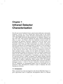
8 Currently there are no physical implementations of the OCh, OMS and OTS layers. As they are defined and implemented, they will be included in this Tutorial . - 8 - Thus the main implementation of OTH is that described in and 4 Where is it standardized for The Optical Transport Network architecture as specified in ITU-T defines two interface classes: Inter-domain interface (IrDI); Intra-domain interface (IaDI). The OTN IrDI interfaces are defined with 3R processing at each end of the interface. This would be the interface between Operators. It could also be thought of as the interface between different Vendors within the same Operator (see Figure 1). 3R3R3R3R3R3 ROperator AOperator BUserUserInter-DomainIrDIInter-DomainIrD IInter-DomainIrDIIntra-DomainIaDIIntra-D omainIaDIIntra-DomainIaDIIntra-DomainIaD I Figure 1 IaDI vs. IrDI The IaDI is the interfaces within an Operator or a Vendor domain. applies to information transferred across IrDI and IaDI interfaces.
9 Compliance by itself is not sufficient to guarantee mid-span meet, since it doesn t specify the electrical or Optical interfaces. It is important to note that only defines logical interfaces. 5 Why use OTN OTN offers the following advantages relative to SONET/SDH: Stronger Forward Error Correction More Levels of Tandem Connection Monitoring (TCM) Transparent Transport of Client Signals Switching Scalability OTN has the following disadvantages: Requires new hardware and management system We will discuss the advantages and disadvantages in the following sections. Forward Error Correction (FEC) Forward error correction is a major feature of the OTN. Already SDH has a FEC defined. It uses undefined SOH bytes to Transport the FEC check information and is therefore called a in-band FEC. It allows only a limited number of FEC check information, which limits the performance of the FEC. - 9 - For the OTN a Reed-Solomon 16 byte-interleaved FEC scheme is defined, which uses 4x256 bytes of check information per ODU frame.
10 In addition enhanced (proprietary) FEC schemes are explicitly allowed and widely used. FEC has been proven to be effective in OSNR limited systems as well as in dispersion limited systems. As for non-linear effects, reducing the output power leads to OSNR limitations, against which FEC is useful. FEC is less effective against PMD, however. defines a stronger Forward Error Correction for OTN that can result in up to dB improvement in Signal to Noise Ratio (SNR). Another way of looking at this, is that to transmit a signal at a certain Bit Error Rate (BER) with dB less power than without such an FEC. The coding gain provided by the FEC can be used to: - Increase the maximum span length and/or the number of spans, resulting in an extended reach. (Note that this assumes that other impairments like chromatic and polarization mode dispersion are not becoming limiting factors.) - Increase the number of DWDM channels in a DWDM system which is limited by the output power of the amplifiers by decreasing the power per channel and increasing the number of channels.