Transcription of Optimization of End Milling Parameters under …
1 Optimization of End Milling Parameters under Minimum Quantity Lubrication Using Principal Component Analysis and Grey Relational Analysis J. of the Braz. Soc. of Mech. Sci. & Eng. Copyright 2012 by ABCM July-September 2012, Vol. XXXIV, No. 3 / 253 K. Sundara Murthy Jayam College of Engineering and Technology Department of Mechanical Engineering 636 813 Dharmapuri, Tamil Nadu, India Dr. I. Rajendran Dr. Mahalingam College of Engineering & Technology Department of Mechanical Engineering 642 003 Pollachi, Tamil Nadu, India Optimization of End Milling Parameters under Minimum Quantity Lubrication Using Principal Component Analysis and Grey Relational Analysis Machining is the major reliable practice in accomplishment of metal cutting industries. The accelerated growing competition demands top superior and large quantity with low cost products. Metal working fluids have significant fragment of manufacturing cost and causes ecological impacts and health problems.
2 This work attempts to advance a competent machining alignment with no ecological impacts. The prediction of quality characteristics and enhancement of machining field are consistently accepting great interest in machining sectors to compress the accomplishment costs. In this paper, GA based ANN prediction model proposes to envisage the quality characteristics of surface roughness and tool wear. The comparison of predicted and experimental values acknowledges the precision of the model. The end Milling experiments are conducted beneath minimum quantity lubrication. This paper as well deals with the multiple objective Optimization with principal component analysis, grey relational analysis and Taguchi method. ANOVA was carried out to determine each parameter contribution percentage on quality characteristics. The results show that cutting speed is the most influencing parameter followed by feed velocity, lubricant flow rate and depth of cut.
3 The confirmation tests acknowledge that the proposed multiple-objective methodology is able in determining optimum machining Parameters for minimum surface roughness and tool wear. Keywords: end Milling , MQL, principal component analysis, grey relational analysis, Optimization Introduction1 The metal cutting industries are facing a lot of adverse complexities during machining in particular with attainment of higher surface quality and tool life. David et al. (2006) mentioned that in a machining system, cutting tool is the most diagnostic element. The cutting tools are subjected to acute loads due to rubbing of work and chip, high stress and temperature, and their gradients. Persistent all-encompassing analysis has been carried out to advance the adequacy of cutting tools. Jacob and Joseph (2005) pointed out that the product quality and ability of machining action depend on cutting tool condition.
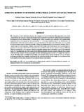
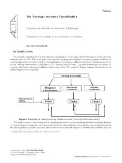
4 The tool wear is provoked by adhesion, abrasion, diffusion and/or oxidation (Lorentzon and Jarvstrat, 2009). Biswas et al. (2008) reported that the tool wear directly influences the power consumption, quality of the surface finish, tool life, productivity, etc. Hence, tool wear leads to poor surface finish, decrease in accuracy and increase in cutting forces, temperature and vibration. Authors (Sundara Murthy and Rajendran, 2010) addressed the surface roughness prediction and analysis forth with the significance and characteristics of machined surface. Figure 1 describes the three stages of cutting tool wear, initial wear stage, progressive wear stage and a rapid wear stage. Micro-cracking is developed and propagated during the initial wear stage, then almost constant in progressive wear stage and added in accelerated amount in rapid wear stage which leads to the cutting tool failure.
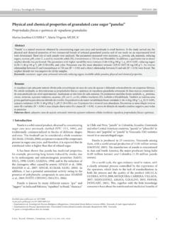
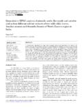
5 The crater and flank wear on the faces of the cutting tool during machining are shown in Fig. 2. Flank wear occurs on relief or flank face of the tool due to abrasion of tool with part machined surface. Generally, it is initiated at the cutting edge and propagated downwards. Crater wear is a concave scar caused by erosion due to sliding of chip on tool rake face. Notch wear is an aggregate of flank and crater which occurs abreast to the intersection of cutting tool and machined Paper received 22 February 2011. Paper accepted 7 October 2011 Technical Editor: Anselmo Diniz surface. Chipping is abatement of micro-particles of tool material. The absolute dismissal of cutting point is alleged as critical failure. But Yong et al. (2007) identified that the flank and crater wears are the major wear patterns. Abrasive wear is a mechanical wear which occurs at low speeds, chiefly due to the scratching of hard impurities of work material.
6 One of the means to abstain this wear is providing harder coating on cutting tool. Adhesive wear is due to strong sticking of work material on the cutting tool surfaces and this can occur at high temperatures and pressures caused by high cutting speeds. High hot hardness and thermal conductivity can reduce the adhesive wear. Diffusion wear is because of atomic transfer between the work and tool materials and can occur in two ways. Tool elements can diffuse into the work material or work elements can diffuse into the tool material. Rajesh (2010) revealed that metallurgical bonding attraction between tool and work material leads to diffusion and this could increase rapidly at elevated temperatures. Nouari and Molinari (2005) acknowledged that the work material flow rate nearest to rubbed area and the average contact temperature between tool-work are the major authoritative factors of diffusion wear.
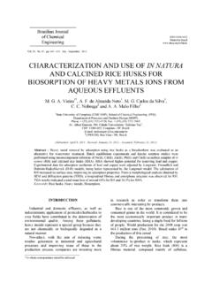
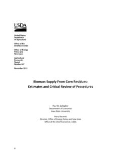
7 Oxidation can be observed on the rack and flank faces of the tool due to high temperatures, atmospheric air and coolant. The oxidation can prevent adhesion and diffusion to a certain extent. The soft oxidation layers are quickly washed out by chip and work, but continuation leads to oxidation wear. Chun (2010) presented that high cutting speed and feed rate could increase the oxidation rate due to reduction of hardness and strength of the tool. The Parameters which could cause the tool wear are shown in Fig. 3. Tool wear has major impact on product quality and process cost. The tool wear also resulted in increased cutting force, cutting temperature, machine vibration and surface roughness. Because of the importance of tool wear, there have been several attempts to foretell and analyze the wear through mathematical and soft computing techniques.
8 Sundara Murthy and Rajendran 254 / Vol. XXXIV, No. 3, July-September 2012 ABCM Figure 1. Various stages of cutting tool wear. Figure 2. Flank and crater wear on the faces of cutting tool. Figure 3. Factors influencing tool wear. Milling tests on titanium alloys with uncoated and coated carbide tool were conducted and performance in terms of tool life and surface quality was evaluated and presented by Nagi et al. (2008). Dimla (2002) machined EN24 with coated inserts; observed wear through vibration signals against time and suggested that the analysis of vibration signals are very effective in tool-wear monitoring. A coherence function model was developed by Mantana and Asa (2008) to describe the relationship between tool wear and tangential and feed vibration components. A fuzzy logic on line monitoring technique was proposed by Susanto and Chen (2003) for face Milling with resultant cutting force and selected machining Parameters and demonstrated its adequacy.
9 Thamizhmnaii et al. (2008) reported that higher flank wear occurred in low cutting speed with high feed rate and depth of cut in turning of SS 440 C stainless steel. A spanking new Transductive-Weighted Neuro-Fuzzy Inference Technique (TWNFIS) was proposed (Agustin et al., 2009) to model tool wear in turning and proved the accuracy by comparing with experimental values. Li et al. (2002) used vibration signals to find out drill wear and proposed a relationship between the vibration and the tool wear with fuzzy neural network model. It was also demonstrated that features of vibration signals can be used to determine the drill wear with greater accuracy. Tansel et al. (2000) proposed cutting force wear relation by Force-variation-based encoding (FVBE) and Segmental-average-based encoding (SABE) methods and proved both are excellent performance in wear estimation.
10 Neural network was applied to predict the wear during hard turning of AISI H-13 steel and the proposed model provided better prediction capabilities (Tugrul and Yigit, 2005). An efficient and successful relationship was established by Choudhury and Bartarya (2003) between tool wear and surface roughness along with cutting temperature. An online tool wear monitoring technique was developed (Silva et al., 1998) with input signals as cutting force, spindle current, sound and vibration in turning and demonstrated efficiency of the suggested technique. Jurkovic et al. (2005) presented direct tool wear measurement methodology using machine vision with 3D picture of tool relief surface. An analytical computation of flank wear was expressed and predicted wear at various cutting speeds was compared with experimental values (Bouzid, 2005). Palanisamy et al.