Transcription of OPTIMIZING PROCESS VACUUM CONDENSERS - …
1 OPTIMIZING PROCESSVACUUM CONDENSERSG raham Box 719,20 Florence AvenueBatavia, 14021-0719 Phone: 716-343-2216 Fax: 716-343-l 097 Email: ; REPRINTED FROM CHEMICAL ENGINEERINGV acuum CONDENSERS play a critical role insupporting VACUUM processing they may appear similar toatmospheric units, VACUUM CONDENSERS havetheir own special designs, considerations andinstallation needs. By adding vacuumcondensers, precondensers andintercondensers (Figure l), system costefficiency can be optimized. Vacuumcondensing systems permit reclamation ofhigh value product by use of a precondenser,or reduce operating costs precondenser placed between the vacuumvessel and ejector system will recovervaluable PROCESS vapors and reduce vaporload to an ejector system minimizing thesystem s capital and operating.
2 An intercondenser positionedbetween ejector stages can condense motivesteam and PROCESS vapors and reduce vaporload to downstream ejectors as well as lowercapital and operating CONDENSERS cannot be designed orconsidered as typical PROCESS heat so will result in less than optimalperformance with increased utility andcondensate treatment costs. For instance,internal geometry may not be modeled wellby standard heat transfer software becausecondenser design is proprietary and variesfrom one manufacturer to another. Also, tube-field layout and baffling are oftenunconventional and not suited for standardsoftware.
3 It is also vital to incorporate ejectoroperation into VACUUM condenser number of primary CPI processes (rangingfrom glycerin manufacture to urea prilling)use VACUUM CONDENSERS each requiring aspecial design that depends on the type ofvacuum condenser needed. For example, inurea plants, the main VACUUM CONDENSERS areoutfitted with spray nozzles above the tubefield for removal of solidified condenser systemsThe prevalent type of VACUUM CONDENSERS areshell-and-tube. These look similar externallyto conventional shell-and-tube heatexchangers; however, their internal geometryis notably different.
4 The major componentsof a VACUUM condenser (Figure 2) include:lTubeslTubesheet( s)lShelllSupport plateslBaffleslChannels or bonnetsThe design and optimum operation of avacuum condenser is application specific, anddetermined by its tube-field layout and flowbaffling. These geometries strongly affectcondensation efficiency and pressure dropminimization. Under sub-atmosphericconditions, the need to minimize pressuredrop is the key design consideration. Pressuredrop across a VACUUM condenser reducescondensation efficiency or product recoveryand, therefore, increases the operating cost ofa VACUUM geometry affects both vapordistribution and flow pattern, whichultimately impacts condenser performanceand pressure drop.
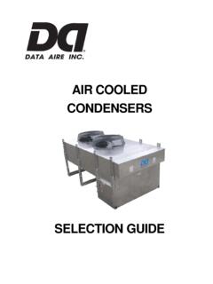
5 Poor flow distributionmay result in localized dead spots in acondenser that essentially reduce effectiveheat transfer surface area. Furthermore,improper baffling may result innoncondensable binding and, consequently, aloss in the system s efficiency and higher VACUUM levels, the design ofvacuum CONDENSERS becomes more critical andthe units are characterized by uniquegeometries or features. For instance, inglycerin plant CONDENSERS , which operatebelow 10 mm Hg, spacing between tubesvaries.
6 Initially, the top tube row has spacingincreased to times tube diameter. Thisallows high specific volume vapors todistribute above the tube field, and flow intothe bundle at velocities suitable for lowpressure drop. Tube spacing is thenOPTIMIZINGPROCESS VACUUMCONDENSERSJ ames R. Lines and David W. Tice, Graham CorporationDesigning theseunits properlyinvolves morethan just usingstandard heat-transfer softwarereduced to a normal times tube diameternear the final tube row, which ensures thatvelocities are sufficiently high to maintainproper heat of VACUUM condensersThe geometries of surface condensersgenerally follow three basic designs thatcomply with standard nomenclatureestablished by the Tubular ExchangerManufacturers Assn.
7 (TEMA; Tarrytown, ):1. Shellside-condensing design fixed tubesheettype, designated as: AXL, BXM, AEL orBEM. Figure 3 provides a clearer descriptionof the various mix and match geometriesand their designations2. Shellside-condensing design removablebundle type: AXS, AXU, AES or AEU3. Tubeside-condensing design fixed tubesheettype: AEL or BEMS hellside condensingKey features of VACUUM CONDENSERS withshellside condensation include:lVapor inlet connectionlVapor distribution space above the tubefieldlMain condensing zonelNoncondensable-gas cooling and finalcondensing zonelNoncondensable-gas outlet connection (orvapor outlet)lCondensate outlet connectionCondensers with shell diameters greater than26 in.
8 Often have a longitudinal baffle thatruns virtually the entire tube length. Thistype of condenser is denoted as a TEMA crossflow X shell. A majority of thecondensation occurs in the tube field prior tothe longitudinal gases and associated vaporsof saturation are drawn underneath thelongitudinal baffle by a low-pressure regioncreated by a downstream ejector, which isdesigned for that purpose. Asnoncondensables and vapors are drawnunderneath the longitudinal baffle, that changein direction separates condensate from thevapors.
9 Condensate drops down via gravityto the bottom of the shell and is subsequentlydrained from the unit. Meanwhilenoncondensables and associated vapors aredrawn through tubes beneath the longitudinalbaffle for additional cooling and separation of condensate fromnoncondensables and remaining vaporspermits final cooling ofnoncondensables to atemperature below thebulk , tubesbeneath a longitudinalbaffle contain the coldestcooling water. Thisenables a system designwhereby finalnoncondensable gas andthe saturated vaporoutlet temperature isbelow the cooling wateroutlet with smallerdiameter shells (less than26 in.)
10 , denoted asTEMA E shells, arecharacterized by up andover baffles in the finalnoncondensable coolingsection. Here again, themajority of condensationtakes place in the tubefield area before the up and over bafflesection. Internal geometry is such that there isseparation of the condensate fromnoncondensables and vapors of noncondensables and associated vaporsof saturation are drawn into the up andover baffle section to ensure that heattransfer is maximized. Once again, it ispossible to cool noncondensables to atemperature below the cooling water outlettemperature or below the average either case of shellside condensing, thedominant design factor is to coolnoncondensables to the coldest temperaturepossible, while at the same time maintainingminimum pressure loss.