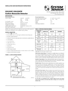
Transcription of OSY2 Supervisory Switch
1 Agency ListingsOSY2 Supervisory SwitchThe System Sensor osy2 is used to monitor the open position of an Outside Screw and Yoke (OS&Y) type gate 3R-rated enclosure User-friendly mounting bracket fits newer valve yokes Single side conduit entry does not require right angle fittings Adjustable length actuator eliminates the need for cutting the shaft Accommodates up to 12 AWG wire Three position Switch monitors vandal and valve close signals Two SPDT contacts are enclosed in a durable terminal block for added strength100 percent synchronization activates both alarm panel and local bell simultaneouslyRobust
2 Construction. The osy2 consists of a rugged housing, intended for indoor and outdoor use. When installed with the actuator in the vertical position, the osy2 is NEMA 3R rated per Flexibility. The osy2 features a user-friendly mounting bracket and adjustable shaft to permit mounting to most OS&Y valves , ranging in size from 1 to 12 . Its right angle design and wide bracket span provides maximum clearance for valve components, to accommodate troublesome valves . Removing the osy2 s gate valve bracket allows the unit to monitor side-bracket-style pressure reducing Operation.
3 Installation is made easier with the osy2 s single side conduit entrance. By providing a direct conduit pathway to the electrical source, right angle fittings are not required. Installation is further simplified by the osy2 s adjustable length actuator, which eliminates the need for cutting the Performance. The osy2 is equipped with tamper-resistant cover screws to prevent unauthorized entry. Inside, two sets of SPDT (Form C) synchronized switches are enclosed in a durable terminal block to assure reliable 93 E3825 Ohio Avenue St.
4 Charles, IL 60174 Phone: 800-SENSOR2 Fax: 630-377-6495 2009 System specifications subject to change without notice. Visit for current product information, including the latest version of this data 1/09 #1960 THE FOLLOWING ARE EXAMPLES OFACCEPTABLE MOUNTING POSITIONS:THE FOLLOWING MOUNTINGPOSITION IS NOT ACCEPTABLE:ACTUATORVERTICAL (DOWN)ACTUATORHORIZONTALACTUATOR VERTICAL(POINTING UP)Electrical Connections for osy2 Ordering InformationPart Screw and Yoke valve Supervisory switchOSY2 AOutside Screw and Yoke valve Supervisory Switch (ULC model)AccessoriesOSYRKR eplacement hardware kit (wrenches, screw pack and J hooks)
5 WFDWR eplacement tamper-proof wrench for cover546-7000 Cover tamper Switch kitHEXWR eplacement hex wrenchS07-66-XXTamper screws for coverOSY2 SpecificationsArchitectural/Engineering SpecificationsModel shall be model number osy2 Supervisory Switch as manufactured by System Sensor. osy2 shall be installed on each valve as designated on the drawings and/or as specified herein. Switches shall be mounted so as not to interfere with the normal operation of the valve and shall be adjusted to operate within two revolutions of the valve control or when the stem has moved no more than one-fifth of the distance from its normal position.
6 The mechanism shall be contained in a weatherproof die cast metal housing that provides a side entrance for conduit and incorporates the necessary facilities for attachment to the valve. A grounding provision is provided. The Switch assembly shall include two switches each with a rated capacity of 10 Amp @ 125/250 VAC and Amp @ 24 VDC. The cover shall contain tamper-resistant screws for which a security wrench will be provided with each Switch . The osy2 shall be Underwriters Laboratories listed for indoor or outdoor use.
7 The osy2 shall be Factory Mutual, CSFM, and MEA SpecificationsOperating SpecificationsOverall Switch Dimensions5 H x 3 W x 3 D ( x x )Contact RatingsTwo sets of SPDT (Form C) A @ 125/250 VAC; @ 6/12/24 VDCS hipping lbs. ( kg)Enclosure RatingUL indoor/outdoor NEMA 3R when mounted with the actuator verticalOperating Temperature Range32 F to 120 F ( 0 C to 49 C) NOTE: The osy2 will operate from 40 F to 120 F ( 40 C to 49 C); however UL does not test control valve Supervisory switches below 32 F (0 C).
8 Cover Tamper SwitchStandard with ULC model Optional for UL model, part no. 546-7000 Maximum Stem Extension25/8 ( )Service UseAutomatic Sprinkler: NFPA 13 One or Two Family Dwelling: NFPA 13D Residential Occupancies up to 4 stories: NFPA 13R National Fire Alarm code: NFPA 72 Bracket Span H x 6 W x 1 D ( x x )Warranty3 yearsConduit EntrancesOne single side open for Patent ,478,038; 5,213,205 osy2 MountingThe following are examples of acceptable mounting positions:The following mounting position is not acceptable:Actuator Vertical (Down)Actuator HorizontalActuator Vertical(Pointing Up)TOP VIEWSWITCH 1 COMCOMABBASWITCH 2 CONTACT RATINGS125/250 VAC24 VDC10 AMPSSUP.
9 SWITCHBBCOMCOMSUP. Switch BBCOMCOMTYPICAL FACP CONNECTIONTO NONSILENCEABLEINITIATING ZONEOF LISTED FACPEND-OF-LINERESISTORBCOMTO POWERSOURCECOMPATIBLEWITH BELLLOCALBELLTYPICAL LOCAL BELL CONNECTIONBREAK WIRE AS SHOWN FOR SUPERVISIONOF CONNECTION. DO NOT ALLOW STRIPPEDWIRE LEADS TO EXTEND BEYOND SWITCHHOUSING. DO NOT LOOP GAUGENOTE: COMMON AND B CONNECTIONS WILL CLOSE WHEN VALVE MOVES 1/5 OF ITS TOTAL TRAVEL FOLLOWING ARE EXAMPLES OFACCEPTABLE MOUNTING POSITIONS:THE FOLLOWING MOUNTINGPOSITION IS NOT ACCEPTABLE:ACTUATORVERTICAL (DOWN)ACTUATORHORIZONTALACTUATOR VERTICAL(POINTING UP)