Transcription of OVERVIEW ISSI
1 IS42/45S81600F IS42/45S16800 FIntegrated silicon Solution, Inc. 1 Rev. D07/17/2015 Copyright 2015 integrated silicon Solution, Inc. All rights reserved. issi reserves the right to make changes to this specification and its products at any time with-out notice. issi assumes no liability arising out of the application or use of any information, products or services described herein. Customers are advised to obtain the latest version of this device specification before relying on any published information and before placing orders for products. integrated silicon Solution, Inc. does not recommend the use of any of its products in life support applications where the failure or malfunction of the product can reasonably be expected to cause failure of the life support system or to significantly affect its safety or effectiveness.
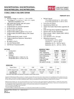
2 Products are not authorized for use in such applications unless integrated silicon Solution, Inc. receives written assurance to its satisfaction, that:a.) the risk of injury or damage has been minimized;b.) the user assume all such risks; andc.) potential liability of integrated silicon Solution, Inc is adequately protected under the circumstancesFEATURES Clock frequency: 200, 166, 143 MHz Fully synchronous; all signals referenced to a positive clock edge Internal bank for hiding row access/precharge Power supply Vdd Vddq IS42/45S81600F IS42/45S16800F LVTTL interface Programmable burst length (1, 2, 4, 8, full page) Programmable burst sequence: Sequential/Interleave Auto Refresh (CBR) Self Refresh 4096 refresh cycles every 16 ms (A2 grade) or 64 ms (Commercial, Industrial, A1 grade) Random column address every clock cycle Programmable CAS latency (2, 3 clocks) Burst read/write and burst read/single write operations capability Burst termination by burst stop and precharge command Temperature Ranges.
3 Commercial (0oC to +70oC) Industrial (-40oC to +85oC) Automotive, A1 (-40oC to +85oC) Automotive, A2 (-40oC to +105oC)OVERVIEWISSI's 128Mb Synchronous DRAM achieves high-speed data transfer using pipeline architecture. All inputs and outputs signals refer to the rising edge of the clock 128Mb SDRAM is organized as follows. 16Mx8, 8Mx16 128Mb SYNCHRONOUS DRAMJULY 2015 KEY TIMING PARAMETERSP arameter -5 -6 -7 UnitClk Cycle Time CAS Latency = 3 5 6 7 ns CAS Latency = 2 10 10 nsClk Frequency CAS Latency = 3 200 166 143 Mhz CAS Latency = 2 100 100 133 MhzAccess Time from Clock CAS Latency = 3 5 ns CAS Latency = 2 nsIS42/45S81600F IS42/45S16800F 4M x8 x4 Banks 2M x16 x4 Banks 54-pin TSOPII 54-pin TSOPII 54-ball BGA 2 integrated silicon Solution, Inc.
4 Rev. D07/17/2015IS42/45S81600F, IS42/45S16800 FDEVICE OVERVIEWThe 128Mb SDRAM is a high speed CMOS, dynamic random-access memory designed to operate in Vdd and Vddq memory systems containing 134,217,728 bits. Internally configured as a quad-bank DRAM with a synchronous interface. Each 33,554,432-bit bank is orga-nized as 4,096 rows by 512 columns by 16 bits or 4,096 rows by 1,024 columns by 8 128Mb SDRAM includes an AUTO REFRESH MODE, and a power-saving, power-down mode. All signals are registered on the positive edge of the clock signal, CLK. All inputs and outputs are LVTTL 128Mb SDRAM has the ability to synchronously burst data at a high data rate with automatic column-address generation, the ability to interleave between internal banks to hide precharge time and the capability to randomly change column addresses on each clock cycle during burst self-timed row precharge initiated at the end of the burst sequence is available with the AUTO PRECHARGE function enabled.
5 Precharge one bank while accessing one of the other three banks will hide the precharge cycles and provide seamless, high-speed, random-access read and write accesses are burst oriented starting at a selected location and continuing for a programmed number of locations in a programmed sequence. The registration of an ACTIVE command begins accesses, followed by a READ or WRITE command. The ACTIVE command in conjunction with address bits registered are used to select the bank and row to be accessed (BA0, BA1 select the bank; A0-A11 select the row). The READ or WRITE commands in conjunction with address bits registered are used to select the starting column location for the burst READ or WRITE burst lengths consist of 1, 2, 4 and 8 locations or full page, with a burst terminate option.
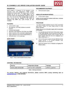
6 CLKCKECSRASCASWEA9A8A7A6A5A4A3A2A1A0BA0B A1A10 COMMANDDECODER&CLOCKGENERATORMODEREGISTE RREFRESHCONTROLLERREFRESHCOUNTER SELFREFRESHCONTROLLERROWADDRESSLATCHMULT IPLEXERCOLUMNADDRESS LATCHBURST COUNTERCOLUMNADDRESS BUFFERCOLUMN DECODERDATA INBUFFERDATA OUTBUFFERDQML DQMHDQ 0-15 VDD/VDDQVss/VssQ121291212916161616512(x 16)409640964096 ROW DECODER4096 MEMORY CELLARRAYBANK 0 SENSE AMP I/O GATEBANK CONTROL LOGICROWADDRESSBUFFERA112 FUNCTIONAL BLOCK DIAGRAM (FOR 2MX16X4 BANKS ONLY) integrated silicon Solution, Inc. 3 Rev. D07/17/2015IS42/45S81600F, IS42/45S16800 FVDDDQ0 VDDQNCDQ1 VSSQNCDQ2 VDDQNCDQ3 VSSQNCVDDNCWECASRASCSBA0BA1A10A0A1A2A3 VDD1234567891011121314151617181920212223 2425262754535251504948474645444342414039 3837363534333231302928 VSSDQ7 VSSQ NCDQ6 VDDQNCDQ5 VSSQNCDQ4 VDDQNCVSSNCDQMCLKCKENCA11 A9 A8A7 A6A5A4 VSSPIN CONFIGURATIONS54 pin TSOP - Type II for x8 PIN DESCRIPTIONS A0-A11 Row Address InputA0-A9 Column Address InputBA0, BA1 Bank Select AddressDQ0 to DQ7 Data I/OCLK System Clock InputCKE Clock EnableCS Chip SelectRAS Row Address Strobe CommandCAS Column Address Strobe CommandWE Write EnableDQM Data Input/Output MaskVdd PowerVss GroundVddq Power Supply for I/O PinVssq Ground for I/O PinNC No Connection4 integrated silicon Solution, Inc.
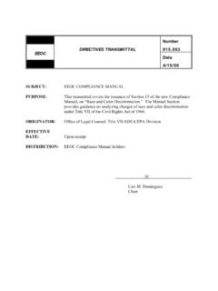
7 Rev. D07/17/2015IS42/45S81600F, IS42/45S16800 FPIN CONFIGURATIONS54 pin TSOP - Type II for x16 PIN DESCRIPTIONS A0-A11 Row Address InputA0-A8 Column Address InputBA0, BA1 Bank Select AddressDQ0 to DQ15 Data I/OCLK System Clock InputCKE Clock EnableCS Chip SelectRAS Row Address Strobe CommandCAS Column Address Strobe CommandVDDDQ0 VDDQDQ1DQ2 VSSQDQ3DQ4 VDDQDQ5DQ6 VSSQDQ7 VDDDQMLWECASRASCSBA0BA1A10A0A1A2A3 VDD1234567891011121314151617181920212223 2425262754535251504948474645444342414039 3837363534333231302928 VSSDQ15 VSSQ DQ14 DQ13 VDDQDQ12DQ11 VSSQDQ10DQ9 VDDQDQ8 VSSNCDQMHCLKCKENCA11 A9 A8A7 A6A5A4 VSSWE Write EnableDQML x16 Lower Byte, Input/Output MaskDQMH x16 Upper Byte, Input/Output MaskVdd PowerVss GroundVddq Power Supply for I/O PinVssq Ground for I/O PinNC No ConnectionIntegrated silicon Solution, Inc.
8 5 Rev. D07/17/2015IS42/45S81600F, IS42/45S16800 FPIN CONFIGURATION54-ball BGA for x16 (Top View) ( mm x mm Body, mm Ball Pitch)PACKAGE CODE: 54B (8x8) 1 2 3 4 5 6 7 8 9 ABCDEFGHJVSSDQ14DQ12DQ10DQ8 DQMHNCA8 VSSDQ15DQ13DQ11DQ9 NCCLKA11A7A5 VSSQVDDQVSSQVDDQVSSCKEA9A6A4 VDDQVSSQVDDQVSSQVDDCASBA0A0A3DQ0DQ2DQ4DQ 6 DQMLRASBA1A1A2 VDDDQ1DQ3DQ5DQ7 WECSA10 VDDPIN DESCRIPTIONSA0-A11 Row Address InputA0-A8 Column Address InputBA0, BA1 Bank Select AddressDQ0 to DQ15 Data I/OCLK System Clock InputCKE Clock EnableCS Chip SelectRAS Row Address Strobe CommandCAS Column Address Strobe CommandWE Write EnableDQML x16 Lower Byte Input/Output MaskDQMH x16 Upper Byte Input/Output MaskVdd PowerVss GroundVddq Power Supply for I/O PinVssq Ground for I/O PinNC No Connection6 integrated silicon Solution, Inc.
9 Rev. D07/17/2015IS42/45S81600F, IS42/45S16800 FPIN FUNCTIONS Symbol Type Function (In Detail) A0-A11 Input Pin Address Inputs: A0-A11 are sampled during the ACTIVE command (row-address A0-A11) and READ/WRITE command (column address A0-A9 (x8), or A0-A8 (x16); with A10 defining auto precharge) to select one location out of the memory array in the respective bank. A10 is sampled during a PRECHARGE command to determine if all banks are to be precharged (A10 HIGH) or bank selected by BA0, BA1 (LOW). The address inputs also provide the op-code during a LOAD MODE REGISTER command. BA0, BA1 Input Pin Bank Select Address: BA0 and BA1 defines which bank the ACTIVE, READ, WRITE or PRECHARGE command is being applied. CAS Input Pin CAS, in conjunction with the RAS and WE, forms the device command. See the "Command Truth Table" for details on device commands.
10 CKE Input Pin The CKE input determines whether the CLK input is enabled. The next rising edge of the CLK signal will be valid when is CKE HIGH and invalid when LOW. When CKE is LOW, the device will be in either power-down mode, clock suspend mode, or self refresh mode. CKE is an asynchronous input. CLK Input Pin CLK is the master clock input for this device. Except for CKE, all inputs to this device are acquired in synchronization with the rising edge of this pin. CS Input Pin The CS input determines whether command input is enabled within the device. Command input is enabled when CS is LOW, and disabled with CS is HIGH. The device remains in the previous state when CS is HIGH. DQML, Input Pin DQML and DQMH control the lower and upper bytes of the I/O buffers. In read DQMH mode,DQML and DQMH control the output buffer. WhenDQML orDQMH is LOW, the corresponding buffer byte is enabled, and when HIGH, disabled.