Transcription of OWNER’S MANUAL Close Coupled Motor Driven …
1 owner S MANUAL Close Coupled Motor Driven Centrifugal Pump6811 0413 2013 Pentair Ltd. All Rights Reserved. BE987 (07/01/13)STA-RITE DE MEXICO MOnTERREy, , MEXICOPH: +52(81)8151-6102 | EMAIL: General Information .. 4-5 Pump Foundation ..5 Centrifugal Pump Suction Connection ..6-9 Swimming Pool Pump Suction Connection ..10-11 Discharge Connection ..12-13 Electrical Connection ..14 START-UP General Information ..15 Determine Pump Rotation ..16 Pump Priming ..17 MAINTENANCE Mechanical Shaft Seal ..18-20 PUMP NOMENCLATURE General Information ..21 Parts Breakdown ..22 TROUBLESHOOTING ..23 WARRANTY ..24 Page Table of Contents 2 READ AND FOLLOW SAFETY INSTRUCTIONS!This is the safety alert symbol.
2 When you see this symbol on your pump or in this MANUAL , look for one of the following signal words and be alert to the potential for personal injury:warns about hazards that will cause serious personal injury, death or major property damage if about hazards that will or can cause serious personal injury, death or major property damage if about hazards that will or can cause minor personal injury or property damage if label NOTICE indicates special instructions which are important but not related to Proposition 65 WarningThis product and related accessories contain chemicals known to the State of California to cause cancer, birth defects or other reproductive read and follow all safety instructions in this MANUAL and on safety labels in good condition.
3 Replace missing or damaged safety SafetyWire Motor for correct voltage. See Electrical section of this MANUAL and Motor Motor before connecting to power National Electrical Code and local codes for all wiring instructions in this MANUAL when connecting Motor to power SafetyDo not allow pump, piping, or any other system component containing water to freeze. Freezing may damage system, leading to injury or flooding. Allowing pump or system components to freeze will void approved liquids only with this inspect pump and system safety glasses at all times when working on work area clean, uncluttered and properly lighted; store properly all unused tools and visitors at a safe distance from the work workshops childproof; use padlocks and master switches; remove starter Pool and Spa Installation SafetyIncorrectly installed or tested equipment may fail, causing severe injury or property damage.
4 Read and follow instructions in owner s MANUAL when installing and operating equipment. Have a trained pool professional perform all pressure Do not connect system to a high pressure or city water Install pump with at least 2 hydraulically balanced main drains equipped with correctly installed, screw-fastened, anti-entrapment certified covers, at least 3 feel apart, nearest point to nearest point. See Page Trapped air in system can cause explosion. BE SURE all air is out of system before operating or testing pressure testing, make the following safety checks: Check all clamps, bolts, lids, and system accessories before testing. Release all air in system before testing. Tighten Berkeley trap lids to 30 ft.
5 Lbs. ( kg-cm) torque for testing. Water pressure for test must be less than 25 PSI (172 kPa). Water Temperature for test must be less than 100 F. (38 C). Limit test to 24 hours. After test, visually check system to be sure it is ready for operation. Remove trap lid and retighten hand tight only. NOTICE: These parameters apply to Berkeley equipment only. For non-Berkeley equipment, consult voltage. Can shock, burn, or cause pump before connecting to power 3 Heavy weight crushing hazard. NEVER walk or reach under a suspended pump. DO NOT screw an eye bolt into the Motor housing and attempt to lift assembly!
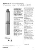
6 The lifting point built into the Motor case is not designed to support the combined weight of the Motor and crane or hoist must have a capacity in excess of the combined weight of the Motor and pump. Use a minimum of two chains or straps to lift Motor /pump assembly. Each chain or strap must have a capacity in excess of the combined weight of the Motor and / PUMP LIFTING PROCEDURE:Wrap the first chain or strap under the fan end of the Motor up tight against the Motor feet, and the second chain or strap under the pump bracket between the pump end and the Motor /pump assembly slowly to ensure that the chains or straps will not slip when put under tension.
7 Balance Motor and pump with chains or straps to maintain proper weight distribution. If not balanced, release tension on the chains or straps and 0497 Installation General Information 4 General InformationLOCATION:Locate the pump as near the water source as practical. Make the pipe run as short and straight as possible, especially if a suction lift is attention should be taken to assure that net positive suction head available (NPSHA) exceeds net positive suction head required (NPSHR) by the pump or reduced performance and severe pump damage may result. If in doubt, check with your nearest Berkeley professional dealer. Install pump in a clean, dry and drained location readily accessible for inspection and maintenance.
8 Provide ample : Refer to illustrations at weights. Use care and proper equipment when handling pump for installation. Pump should be set on a concrete foundation which is sufficiently substantial to absorb vibration and which provides a permanent and rigid :System piping should be at least one commercial pipe size larger than pump connections and flow velocity should not exceed eight (8) feet per second. In pool installation, flow velocity should not exceed six (6) feet per : Take care to align piping with pump case. Misalignment or excessive pipe strain can cause distortion of pump components resulting in rubbing, breakage and reduced pump life.
9 Support pipe in such a way that no force is exerted on pump connections. Check alignment as follows: with the pump shut down and isolation valves closed, remove pipe flange bolts. If the mating flanges come apart or shift, misalignment is present and causing pressure on the connections. Adjust pipe supports until flanges mate without any force. This procedure can be done throughout piping PIPING:Refer to Pages 10 and 11 for installation instructions for swimming pool circulating pump applications. Refer to Pages 6 through 9 for recommended and not recommended practices in suction connections in centrifugal PIPING:Refer to illustrations on Page 12 and 13 for recommended and not recommended practices in discharge connections.
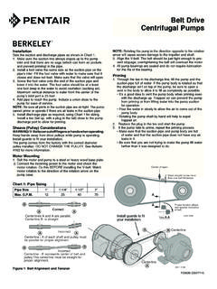
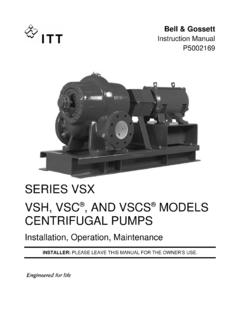
10 ELECTRICAL CONNECTION: Hazardous voltage. Can shock, burn, or cause death. All wiring should be done by a qualified electrician. Disconnect power to pump before voltage and phase stamped on pump Motor nameplate before wiring. Be sure they agree with your electric current supply. They MUST be the same. If in doubt, check with your local power to illustration on Page 14 for minimum recommended pumping panel components that help safeguard your pump during Foundation797 0212 Pump or Motor Frame1/2" or thickerSole Plate tappedfor hold down boltsAnchorBoltsConcrete FoundationPump or Motor FrameAlignmentShimsAnchorBoltSteelChanne lConcreteFoundationGroutGroutDamDrainage WedgesVarious HeightsTackWeldConcreteFoundationShims There are several types of permanent pump/ foundation installations in use.