Transcription of Panic Device - First Choice Building Products
1 Rev. 031510 TMPanic DevicePower ControllerInstallation Guide- 2-SP-500 Table of Contents:Overview .. 3 Specifications .. 3 Installation Instructions .. 3 LED Diagnostics .. 4 Maintenance ..4 Terminal Identification .. 4 Wiring Distance Table .. 5 Enclosure Dimensions .. 7SP-500- 3-Installation Instructions:Wiring methods shall be in accordance with the National Electrical Code/NFPA 70/NFPA 72/ANSI, and with all localcodes and authorities having jurisdiction. Product is intended for indoor use Mount unit in desired location within protected premises (Maximum Wiring Distance Table, pg. 5). Mark and predrill holes in the wall to line up with the top two keyholes in the enclosure. Install two upper fasteners and screws in the wall with the screw heads protruding.
2 Place the enclosure s upper keyholes over the two upper screws, level and secure. Mark the position of the lower two holes. Remove the enclosure. Drill the lower holes and install the two fasteners. Place the enclosure s upper keyholes over the two upper screws. Install the two lower screws and make sureto tighten all screws (Enclosure Dimensions, pg. 7). Secure cabinet to earth Connect AC power (115 VAC 60Hz) to terminals marked [L, G, N] (Fig. 1, pg. 5 & Fig. 2, pg. 6). The AC LED (Green) will illuminate indicating power is Measure output voltage at terminals marked [-- AUX +] and [-- OUT +] before connecting devices ( , pg. 5 & , pg. 6).This helps avoid potential : Voltage will be present on the output when the unit is not triggered and electric Panic hardware is 24 VDC Panic hardware Device to terminals marked [-- OUT +] (Fig.)
3 1, pg. 5 & Figs. 2 & 2b, pg. 6).Be sure to observe polarity. Voltage should dissipate across output terminals when load is properly Connect Normally Open (NO) Dry Contacts from actuating devices such as an Access Control Panel, REX PIR, Keypad, etc. to terminals marked [GND, NO] (Fig. 1, pg. 5 & , pg. 6).7. Connect auxiliary devices to be powered (Keypads, REX motion detectors, electronic timers, external relays) to the auxiliary power output terminals marked [--AUX +] ( , pg. 5 & , pg. 6). using stand-by batteries, they must be lead acid or gel type. 4AH batteries will provide a 1/2 hour ofbackup time. Connect two (2) 12 VDC batteries wired in series to the terminals marked [-- BAT +].For Access Control applications batteries are optional.
4 When batteries are not used a loss of AC will result in the loss of output voltage (Fig. 2b, pg. 5). Listed tamper switch (Sentrol model 3012 or equivalent) at the top of the enclosure. Slide the tamper switch bracket onto the edge of the enclosure approximately 2 from the right side (Fig. 2a, pg. 6). Connect tamper switch wiring to the Access Control Panel input or the appropriate Listed reporting Device . To activate alarm signal open the door of the completion of wiring secure enclosure door with screws or cam Approval: UL Listed for Access Control System Units (UL 294). CUL Listed - CSA Standard , Signal Equipment. CSFM - California State Fire Marshal : Input 115 VAC 60Hz, 7 amp. One (1) NO trigger : One (1) 24 VDC lock output rated up to 16 amp for 300ms, amp continuous hold current.
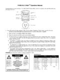
5 * One (1) 24 VDC filtered regulated auxiliary output rated @ amp continuous supply current**Note: Total combined current for the 24 VDC outputsmay not exceed 1 Backup: Built-in charger for sealed lead acid or gel type batteries. Automatic switch over to stand-by battery when AC fails. Maximum charge current .3 amp. When 4AH batteries are used, battery capacity for emergency stand-by is at least a 1/2 Indicators: Green AC Power LED indicates 115 VAC present. Red LED indicates presence of H x W x DOverview:SP-500 operates one (1) 24 VDC Panic hardware Device . It is designed to handle the high current surge Panic hardware lock-ing devices demand. In addition, an auxiliary power output provides power for accessory devices such as card readers, key-pads, REX PIRs, electronic timers, relays, etc.
6 Specifications:- 4-SP-500 LED DiagnosticsMaintenance:Unit should be tested at least once a year for the proper operation as follows:Output Voltage Test:Under normal load conditions the DC output voltage should be checked for proper voltage Test:Under normal load conditions check that the battery is fully charged, check specified voltage both atbattery terminal and at the board terminals marked [-- BAT +] to insure there is no break in the battery connection :Maximum charging current under discharge is :Expected battery life is 5 years, however it is recommended changing batteries in 4 years or less if :For continuous protection against risk of electric shock and fire hazard, replace input fuse with the same typeand rating amp/250V. Do not expose to rain or moisture, indoor use only.
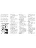
7 Terminal Identification:LEDLED StatusPanic Device Power Controller StatusAC PowerGreenOnNormal operating of output operating normal output is not LegendFunction/Description-- AUX +24 VDC Auxiliary Output @ B AT +24 VDC Stand-by Battery Connection (Two (2) 12 VDC batteries wired in series).-- OUT +Connect 24 VDC Panic Hardware Device , up to 16 amp 300 ms., .5 amp on / NONormally Open [NO] trigger input controls output. A maintained contact closurewill extend the unlock 5---- OUT+ACLEDUNLOCKLGNGNDNO--BAT+--Aux+TrgPa ni c Har dware Device24 VDCRE X PIRA ccessCo nt rolPan el+---Rec har geableBat teri es12 VDC+---12V DC115 VAC pow er mainsno n power- li mi 1 Wiring Distance Table:Typical Application Diagram:InRushCurrentWire GaugeElectric Butt or PivotMax distance from Power Supply to frame side of openingEPTMax distance from Power Supply to frame side of opening8 amp14 AWG Stranded75 amp12 AWG Stranded175 amp14 AWG Stranded60 amp12 AWG Stranded80 amp14 AWG Stranded40 amp12 AWG Stranded60 amp10 AWG Stranded100 6-SP-500 Fig.
8 2 CAUTI ON:De-ene rgize unitpr iorto se rv icing. Fo r continu edprotec tionag ainst ri skof elect ri c shockand firehaza rdreplacemainfu se withthesa no t expose to ra in OUT+LGNT amper Switc hGNDNO--BAT+--Aux+ 2aFig. 2b--- OUT+GNDNO--BAT+--Aux+TrgEdge ofEn clo sureto Access Control Panelor U. L. Lis te dReportin g Dev ic eEncl os ureSe ntr olmo del # 3012 Tamper Swi tc hor equiva lentSP-500- 7-Enclosure H x W x D- 8-SP-500 Special Projects Group is not responsible for any typographical Projects Group Northbrook Parkway, Suite 120, Suwanee, Ga 30024, 678-417-8500, fax: 678-475-8448 web site: Warranty from manufacturer, Made in Rev. 031510G01 JNotes.