Transcription of PerTronix Performance Ignition Systems Installation ...
1 12-VOLT NEGATIVE GROUND INSTRUCTIONSDISTRIBUTOR DISASSEMBLYPRIOR TO Installation TURN Ignition SWITCH OFF OR DISCONNECT THE BATTERY 1. Remove the distributor cap, and rotor. Do not disconnect spark plug wires. Examine cap and rotor for wear or damage. Replace as needed. 2. Disconnect the point wire from the negative (-) terminal of the coil. 3. Remove the point wire, point, and condenser from the The Ignitor does not require any modification to the distributor. Therefore the point, condenser and hardware can be used as backup. 5. Clean all dirt and excess oil from the breaker plate and point cam. Part NumberAir GapPart NumberAir GapPart NumberAir (1)91641N/A91847 (1)91643N/A91941 (1)91661N/A91942 (1)91662N/A9HO-141 (1)91741N/A9MR-145 (1)91761 (1) N/A - IGNITOR II MODULE AND MAGNET SLEEVE AIR GAP IS NOT ADJUSTABLE. (1) - IGNITOR II AND MAGNET SLEEVE AIR GAP CAN BE ADJUSTED ANYWHERE BETWEEN AND.
2 GENERAL INFORMATION1. IMPORTANT: Read all instructions before starting DO NOT USE WITH SOLID CORE SPARK PLUG WIRES. 3. The Ignitor II Ignition can be used in conjunction with most Ignition coils rated at ohms or greater. 4. All external resistors must be removed to achieve optimum Performance from the Ignitor II Ignition system. 5. The Ignitor II is compatible as a trigger for most electronic II INSTALLATION1. Part number 91261 & 91266 only: See Figure 1 to insure that you are installing the correct Ignitor Install the Ignitor II module in the same manner as a set points. Secure in place using the provided hardware. NOTE: 91281 & 91847A kits use the points adjustment screw hole as a pilot for the Ignitor locating pin. Confirm the mounting plate is flat and fits without any Vacuum advance distributors only: If the distributor ground wire was removed during the Installation process be sure it is re-attached securely.
3 NOTE: If the ground wire is missing, one needs to be installed and attached from the point breaker plate to the distributor Insert the Ignitor black and red wires through the distributor housing verifying the grommet is seated properly. 5. Place the magnet sleeve over the distributor shaft, and onto point cam. Press down firmly to insure magnet sleeve is fully seated. NOTE: 91281 kits only: Magnet sleeve must be level with Ignitor II module on top. See Figure INSTRUCTIONS1. The Ignitor II Ignition can be used in conjunction with most Ignition coils rated at ohms or greater. For optimum Performance purchase and install the Flamethrower II high Performance Attach the black Ignitor II wire to the negative coil terminal. Attach the red Ignitor II wire to the positive coil terminal. (See Figure 3)A. Recommended Installation : Many vehicles came equipped with ballast resistor or resistance wire. To achieve optimum Performance from the Ignitor II Ignition system, we recommend removal of these components.
4 To remove a ballast resistor, (normally white ceramic blocks 3 to 4 inches long), dis-connect all wires on both ends of the ballast resistor. Remove the resistor from the vehicle and splice the disconnected wires together at a single point. To remove a resistance wire, trace the coil power wire, which was previously con-nected to the positive coil terminal, back to the fuse block. Bypass this wire with a 12-gauge copper stranded Alternative Installation : The Ignitor II can also be installed in applications retaining the ballast resistor or resistance wire. Attach the Ignitor II black wire to the negative coil terminal. Attach the Ignitor II red wire to the Ignition side of resistance, or any 12 volt Ignition power Check to insure that the polarity is correct, and that all connections are Re-connect the Perform the Power and Ground tests. Refer to the Power and Ground test procedure. 6. Start the engine and allow it to reach normal operat-ing temperature.
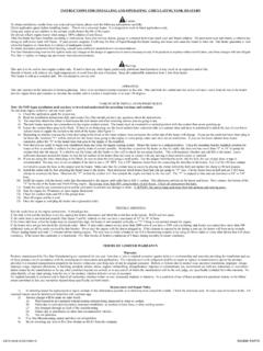
5 Check Ignition timing, and adjust to the desired setting.+-To IgnitionFIGURE 3(WITHOUT EXTERNAL RESISTOR)POWER & GROUND TESTSIt is imperative that the power and grounds be checked as part of the Installation procedure. After installing the Ignitor module and the distributor and with the distributor in the engine, use a digital multi-meter to measure the resistance from the aluminum plate holding the module to battery (-), the net resistance must be less than ohms. (Set meter to lowest ohms setting). The net resistance is the meter reading minus the resistance of the meter leads. If the net resistance is greater than ohms, the source of the faulty ground must be found and fixed. Usually the source of the bad ground is easily found by holding one probe on an original location and moving the second probe toward the static probe. Where the resistance drops identifies the resistance from Ignitor plate to battery negative terminal.
6 OhmsEXAMPLE:Resistance from Ignitor plate to battery negative (-) ohmsResistance of meter ohmsAfter subtracting meter lead resistance, your net resistance ohmsVOLTAGE TEST1. (Do not disconnect wires from Ignition coil). Place Ignition switch in the off Connect a jumper wire from negative (-) terminal of the coil to a good engine the voltmeter red lead to the positive (+) terminal of the coil and the black lead to a good engine the Ignition switch to the on position and note voltage reading on the voltme-ter. Quickly read the voltage and turn Ignition OFF . Leaving Ignition ON for an extended period could result in permanent damage to the SEE CHART BELOW FOR : Low voltage can be caused by poor connections, poor contacts in the Ignition switch, ballast resistor, and or a resistance wire in the wiring harness (Factory Installed).MinimumMaximumIgnition Switch ON Set the air gap between the module and magnet sleeve using the provided plastic feeler gauge ( thick).
7 This done in the same manner as points. 7. Reinstall the rotor, and the distributor cap. Make sure all spark plug wires are securely attached. 8. See Wiring Sleeve Must be level with Ignitor on 2(91281 Kits Only)FIGURE 1 Ignitor 91261 fits distributors with a hollow shaft and a notch cut into the top of the 91266 fits fistributors with a solid shaft and a flat side ( D shape).91261 BIRDSEYE VIEW 91266 BIRDSEYE VIEW