Transcription of Petro 424 Section I PI, IPR Curves Productivity …
1 Petro 424 Section i pi , IPR Curves Productivity index - J - The ratio of the production rate of a well to its drawdown pressure. bpd/psi Drawdown Pressure - p- The pressure drop between the reservoir ( ps) and the flowing bottom hole pressure (pwf). wfsppqJ (1-1) note: q here is the gross liquid production rate in bpd. Ideally pwf for a q is measured using a bottom hole pressure gauge. A build up or drawdown test is used to calculate ps along with other parameters such as a skin factor (s).
2 Equation 1-1 uses these values to get a Productivity index for the well. Using the radial flow equation wowfrrkhqppln007082. (1-2) which gives Jrrkhppqwowf ln007082. (1-3) J or other parameters can be calculated depending on the known data. Example 1-1 A Permo-Penn well is flowing 156 bopd from perforations at 10,454 to 10,468 ft. The bottom hole flowing pressure is recorded at 250 psi and the reservoir pressure is of the field has been recorded at 3410 psi. Find J. Using equation 1-1 J = 156 / 3410 - 250 J=.049 bpd/psi Now calculate the kh if = cp and a formation volume factor of Assuming that the spacing for this depth is 160 acres, a r of 1320 ft and a rw of inches kh = J o ln(r/rw)/.
3 007082 kh =.049* * *ln(1320/.208)/.007082 kh = 197md ft k= 16 md Example 1-2 A field is drilled up on rectangular 80 acre spacing. The reservoir pressure is 1000 psi, the permeability 50 md, the net sand thickness 20 feet, the oil viscosity 3 cp, and the oil formation factor The wells are completed with 7 inch casing. Calculate the J for this well. The distance between wells on 80 acre spacing is 1864 ft, so r can be assumed to be 932 ft, ln(932/.292) = Using equation 1-3 J = .007082 * 50 * 20 / * 3 * J = .234 bpd/psi Skin Effect s The pressure drop caused by the near wellbore skin effect is defined by the equation skhqps 2 (1-4) Add the pressure loss from skin to equation 1-2 srrkhqppwowfln007082.
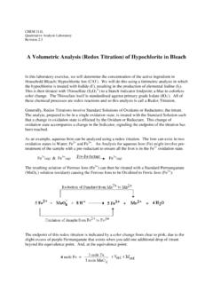
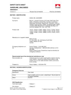
4 (1-5) So equation 1-3 becomes Jsrrkhppqwowf ln007082. (1-6) Ideal PI JI skinwfsIpppqJ bpd/psi (1-7) Actual PI JA wfsappqJ bpd/psi (1-8) Specific PI - Js )(wfsspphqJ bpd/psi/ft (1-9) Effective wellbore radius swwerr / ft (1-10) Productivity index in Horizontal Wells Drainage pattern formed around a horizontal well A schematic of horizontal well drainage area. Generally the length of a horizontal well is much greater than the reservoir thickness. In this case the flow in the well can be described by Lrphkqehhh/4ln1007078. (1-11) This gives: LrhkJehhh/4ln1007078.
5 (1-12) In many cases there is a horizontal-to-vertical permeability anisotropy which effects the flow into the wellbore. For this case )1(ln2/)2/( (1-13) where vhanikkI LrLaeH for L/2 < You can find the equation for Jh. To include skin effect '22)1(ln2/)2/( (1-14) 13411ln1,22max,'wMAXHwHaniseqraraIkks (1-15) aH,max is the largest horizontal axis of the cone of damage. Homework #1 Problem #1 For a well that has the following; Wells are 1980 apart casing 5 1/2 ps = 2100 psi o = = k = 35 md h = 15 ft Find J and Js for this well. Calculate the pwf for a q of 100 bopd and 12 bwpd and also for 300 bopd and 45 bwpd.
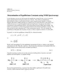
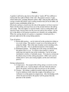
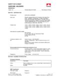
6 Problem #2 Find the J and kh for a well with the following; Same spacing as #1 casing 4 = cp = ps = 3400 psi pwf = 1250 psi qo = 150 bopd qw = 600 bwpd GOR = 1100 ft3/bbl Equation 1-1 can be rewritten as q = J p (1-16) It can be seen that the relationship between q & p is a straight line that passes through the origin. figure 1 Equation 1-1 can also be rewritten as pwf = ps - q/J (1-17) With ps and J constant for any particular instant the plot of q vs BHFP will be a straight line as shown in figure 2. The point when BHFP is zero or at the greatest p is called the well s potential. It is the maximum rate that the well could produce.
7 It is noted that physically a BFP of 0 psi is basically not attainable. 020406080100120140160180 Drawdown psi figure 2 In the olden days this potential was to calculate the allowable for the well in many states. Effects of Water Production Relative permeabilities can be used to calculate separately the flow of both oil and water. ko = kkro kw = kkrw (1-18) kro relative perm to oil krw relative perm to water Since the relative permeabilities are function of the oil and water saturations of the reservoir so are the flow rates of the oil and water. srrpphkqwooowfooln007082. srrpphkqwwwwwfwwln007082. (1-20) 0500100015002000250030003500q bpd Pseudo-Steady State Flow For wells that have a no-flow boundaries. These boundaries can be caused by the production of adjacent wells or a natural boundary, fault or pinchout.
8 These are the equations that are used on older wells. The pressure at the boundary can be calculated by using (1-21) A much more helpful equation would be one that uses the average reservoir pressure which can be obtain in the field by means of a pressure test. This equation is (1-22) (1-21) With the addition of skin (1-22)