Transcription of PFC Mini Power Factor Corrected AC-DC Switcher
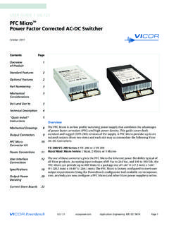
1 UG:115 Applications Engineering: 800 Page 1 PFC MiniTM Power Factor Corrected AC-DC SwitcherUSER GUIDE | UG:115 March 2010 Overview The PFC Mini is an extremely low profile, 1 RU, switching Power supply that combines the advantages of Power Factor correction and high Power density. This design guide covers both standard and rugged chassis COTS (MI) versions of the product. The PFC Mini can provide up to six isolated outputs (three slots) and each slot accommodatesthe following Vicor DC-DC and VI/E-J00 series: One VI/E-200 or Two VI/E-J00 convertersMaxi, Mini Micro series: One Maxi, Two Mini converters (Micros cannot be used)The use of these converters give the PFC Mini the inherent Power flexibility typical of all Vicor products. Using the VSPOC configurator tool available on , anybody can now configure a PFC Mini (and other Vicor Power supplies) online. Accepting input voltages of 85 Vac to 264 Vac, and 100 Vdc to 380 Vdc, the PFC Mini can provide up to 1,500 Watts in a package size of " H (43,6 mm) x 6" W (152,4 mm) x " L (309,9 mm).
2 The PFC Mini is factory configured to meet user : If you have a PFC Mini that shipped from October 2005 onwards, please see Page 19 for more Overview 1of Product Mechanical2 Considerations PFC Mini 3 Do s and Don ts Technical Description 3 PFC Mini 5 Configuration LayoutPart Numbering 6 Quick Install 7 InstructionsMechanical Drawings 10 Output Connectors 11 Interface Connections 12 Output Power 20De-rating Specifications21 Current Share Boards 24 Low Leakage Version 27 Low Output Ripple 27 UG:115 Applications Engineering: 800 Page 2 Standard Features n Power Factor Correction: at 115 Vac; at 230 Vacn Universal Input: 85 264 Vac, 47 500 Hz, or 100 380 Vdcn Power Output: 1,500 W at 230 Vac; 800 W at 115 Vacn Up to 6 isolated outputs (3 slots)n Fan cooledn Full Power to 45 C; half Power at 65 Cn Conducted EMI: VI-200/VI-J00 series: Maxi, Mini, Micro series: FCC Class B FCC Class A EN55022 Class B EN55022 Class A (certain configurations meet EN55022 Class B)n Harmonic Distortion complies with EN61000-3-2n AC Power OK status signaln Autosense (for more information, see Page 8 and Page 14)n Output overcurrent protection on all outputsn Output overvoltage protection (not applicable when using VI-J00)n Output overtemperature limiting (not applicable when using VI-J00)n Ride-through (hold-up) time: >20 ms at 1,200 W load (nominal line)n Size: " H (43,6 mm) x 6" W (152,4 mm) x " L (309,9 mm)n Safety Agency Approvals: CE Mark, cT Vus, UL (Note.)
3 Certain MI chassis may not carry all safety certs)Optional Features n Extended temperature range output convertersn Current share board - see Page 24n RAM modules for low noise applications - see Page 27n Connector kit available (#19-130047)n Low leakage available - see Page 27n Office environment fan - see Page 27n MI chassis specific options - Mil-STD 810 for Shock and Vibration - Mil-STD 704 and 1399 for overvoltage and transients - -40 C Operation - Conformal coating - contact factoryMechanical ConsiderationsThe PFC Mini can be mounted on either of two surfaces using standard 8-32 (4 mm) size screws. Maximum allowable torque is in. lbs., and the maximum penetration is in. (4 mm). UG:115 Applications Engineering: 800 Page 3 When selecting a mounting location and orientation, the unit should be positioned so airflow is not restricted. Maintain a 2" (5,1 cm) minimum clearance at both ends of the PFC Mini, and route all cables so airflow is not obstructed.
4 The Power supply draws air in at the fan side/AC input side and exhausts air out the load side. If airflow ducting is used, avoid sharp turns that could create back pressure. The fans move approximately 20 CFM of excessive bending of output Power cables after they are connected to the output terminals. For high-current outputs, use cable ties to support heavy cables and minimize mechanical stress on connectors. Be careful not to short-out to neighboring outputs. The maximum torque recommended on output nuts is 10 in. applications in which the unit is exposed to excessive shock or vibration levels. In such applications, a shock-absorbing mount design is Mini Do s and Don tsn If Sense jumpers are removed, do not leave Sense lines open (especially if unit does not have Autosense). Sense lines must be terminated to their respective outputs. Use twisted pair 20-22 AWG wire when installing Remote NEVER disconnect the +Out and -Out load wires while the supply is operating as disconnecting WILL cause damage to the Power supply.
5 Ensure load wires connected before remote sense To prevent damage to supply, verify polarity of remote sense connection before turning supply Always turn the Power supply off before disconnecting input or output Do not restrict airflow to the unit. The cooling fan draws air into the unit and forces it out at the output Run the output (+/ ) Power cables next to each other to minimize Do not repair or modify the Power supply in any manner. Doing so will void the warranty. Contact Insert proper fault protection at Power supply input terminals ( , a fuse).n Use proper size wires to avoid overheating and excessive voltage Output voltages over 60 Vdc, whether from individual modules or series arrays, are considered as hazardous secondary outputs under UL60950. Appropriate care must be taken in design implementation of the DescriptionThe PFC Mini consists of an offline single phase, Power - Factor - Corrected front end, EMI filter, cooling fan, customer interface, associated housekeeping circuits, and a selection of Vicor s DC-DC AC mains voltage is applied to a terminal block.
6 The input current is passed through an EMI filter designed to meet conducted noise limit B specifications in FCC Part 15 and EN55022, Class B (with VI-200/VI-J00 series modules. If Maxi, Mini, Micro series modules are used, it meets FCC Class A and EN55022 Class A. (Certain configurations meet Class B).At start-up, inrush current is limited by a PTC thermistor. The PTC is shunted out shortly after initial Power -up by a DC bus voltage sense circuit driving a relay. After rectification, the input voltage is put through a boost converter that keeps the AC input current sinusoidal and synchronized with the input AC voltage (in compliance with UG:115 Applications Engineering: 800 Page 4EN61000-3-2). The boost converter delivers a regulated input to the hold-up capacitors and a high-voltage backplane. The backplane supplies Power to the DC-DC converters that provide the desired low voltage regulated conversion is achieved by Vicor s family of zero-current switching (ZCS) DC-DC converters.)
7 These are forward converters in which the main switching element switches at zero current. This patented topology has a number of unique attributes: low switching losses; high frequency operation, resulting in reduced size for magnetics and capacitors; excellent line and load regulation; wide adjustment range for output; low EMI/RFI emission and high initial Power -up, the PFC Mini outputs are disabled to limit the inrush current and to allow the DC bus potential to settle out to the correct operating level. A low- Power flyback converter operating with PWM current-mode control converts the high voltage DC bus into regulated low voltage to Power the internal housekeeping circuits and DC cooling internal housekeeping VCC comes up within two seconds after the application of input Power . Once the high voltage bus is within operating limits, the AC Power OK signal asserts to a TTL "1," indicating the input Power is OK, and enables the Power outputs.
8 An auxiliary VCC output of 5 Vdc sourcing up to A is provided for peripheral output Enable/Disable function is provided by using an optocoupler to control Vicor s DC-DC converters. If the Enable/Disable control pin is pulled low, the optocoupler turns on and disables the output. The nominal delay associated for an output to come up when measured from release of the Enable/Disable pin is 5-10 ms. The General Shutdown function controls all outputs simultaneously and works in a similar FilterRectifierSoft Start CircuitBoost ConverterPFC ControlE/D ControlOutput Card #1 Output Card #2 Output Card #3 FanIsolatedHousekeeping PowerCustomer InterfacePower OutputPower OutputPower OutputInputHigh Voltage BusEnable/Disable ControlCurrent SampleWaveform SampleFigure 1. UG:115 Applications Engineering: 800 Page 5 PFC Mini Configuration LayoutShown above, are two sample PFC Mini configuration layouts.
9 Due to the configurability nature of the PFC Mini, various output combinations are possible. See Page 12 for more information about your output connections. The PFC Mini has three slots and each slot accommodates either full or half-brick note that the maximum output Power of the PFC Mini is 1,500 W at 230 Vac, 800 W at 115 Vac, irrespective of the maximum output Power of the modules if a PFC Mini is configured with three Maxi modules, on the configuration sheet, the maximum output Power of the module (600 W) is listed. However, irrespective of the maximum output Power of the three Maxi modules (1,800 W), the maximum output Power of the PFC Mini is still 1,500 W at 230 Vac and 800 W at 115 populated with 12 V modules, the maximum output Power per slot is 500 W (with other modules it is 600 W). Hence, when a 12 V Maxi module is used, the maximum output Power is limited to 500 W. If a 12 V Mini module is used, the maximum output Power is limited to 250 inputFanS2-M1S1-M1 Slot 1 Slot 2 Slot 3 FanAC inputFanS3-M2S3-M1S2-M1S1-M1 Slot 1 Slot 2 Slot 3S3-M1 UG:115 Applications Engineering: 800 Page 6E/D = Enable/DisablePart NumberingPFC Mini PMx1-x2 x (x4)-xxxx(-x5)(-x6) eg.
10 PM4-22-2988 PM1-03B-48 PM3-03-2643-2 PM6-60-2888-2-QF PM = PM x1 = number of outputs x2 = number of VI-200/VI-J00 x3 = number of Maxi, Mini x4 = optional - standard product designator xxxx = configuration/customer specific # assigned by Vicor x5 = optional factory assigned note - MI = rugged chassis + MC for conformal coated rugged x6 = additional option codes revised to orginal configuration - QF = quiet fan/office enviornment LL = low leakage Output #1VI-J60-CYE/D#3 Output #2VI-J63-CW-SE/D#3V375A5C400BN4E/D#2V375 A5C400BN4E/D#1 SLOT#3 SLOT#2 SLOT#1 Configuration Example:* Actual module part numbers may vary depending on customer (M2)VI-J60-CY-S* (M1)V375A5C400BN4*2V375A5C400BN4* # (M2) (M1) #-S*-S UG:115 Applications Engineering: 800 Page 7 PFC MegaPAC Quick Install Instructions (For Mechanical Drawing, see Page 10)Mounting the PFC Mini n Mount the PFC Mini on either of two Use #8-32 or 4 mm mounting screws.
