Transcription of Photoelectric Smoke Detectors - System Sensor
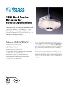
1 Agency ListingsPhotoelectricSmoke DetectorsSystem Sensor i3 series Smoke Detectors represent significant advancement in conventional detection. The i3 family is founded on three principles: installation ease, intelligence, and instant detector line, mounting base included Large wire entry port In-line terminals with SEMS screws Mounts to octagonal and single-gang back boxes, 4-square back boxes, or direct to ceilingStop-Drop N Lock attachment to base Removable detector cover and chamber Built-in remote maintenance signaling Drift compensation and smoothing algorithms Simplified sensitivity measurement Wide-angle, dual-color LED indication Loop testing via EZ Walk feature Built-in test switch Installation ease. The i3 line redefines installation ease with its plug-in design. This allows an installer to pre-wire bases (included with heads). The large wire entry port and in-line terminals provide ample room for neatly routing the wiring inside the base.
2 The base accommodates a variety of back box mounting methods as well as direct mounting with drywall anchors. To complete the installation, i3 heads plug into the base with a simple Stop-Drop N Lock i3 Detectors offer a number of intelligent features to simplify testing and maintenance. Drift compensation and smoothing algorithms are standard with the i3 line to minimize nuisance alarms. 2-wire i3 Detectors can generate a remote LED-indicated maintenance signal when connected to the 2W-MOD2 loop test/maintenance module or a panel equipped with the i3 protocol. The SENS-RDR, a wireless device, displays the sensitivityof i3 Detectors in terms of percent-per-foot inspection. The i3 series provides wide-angle red and green LED indicators for instant inspection of the detector s condition: normal standby, out-of-sensitivity, alarm, or freeze trouble. When connected to the 2W-MOD2 loop test/maintenance module or a panel with the i3 protocol, the EZ Walk loop test feature is available on 2-wire i3 Detectors .
3 This feature verifies the initiating loop wiring by providing LED status indication at each :1523011446S91131809323825 Ohio Avenue St. Charles, IL 60174 Phone: 800-SENSOR2 Fax: 630-377-6495 2009 System specifications subject to change without notice. Visit for current product information, including the latest version of this data 6/09 #2169 Ordering InformationModelThermalWiringAlarm Current2W-BNo2-wire130 mA max. limited by control panel2WT-BYes2-wire130 mA max. limited by control panel4W-BNo4-wire20 mA @ 12 V, 23 mA @ 24 V4WT-BYes4-wire20 mA @ 12 V, 23 mA @ 24 VAccessories2W-MOD22-wire loop test / maintenance moduleRTRemoval / replacement toolSENS-RDRS ensitivity readerA77-AB2 Retrofit adapter bracket, inch ( cm) diameter Smoke Detector SpecificationsArchitectural/Engineering SpecificationsSmoke detector shall be a System Sensor i3 Series model number_____, listed to Underwriters Laboratories UL 268 for Fire Protection Signaling Systems.
4 The detector shall be a Photoelectric type (Model 2W-B, 4W-B) or a combination Photoelectric /thermal (Model 2WT-B, 4WT-B) with thermal Sensor rated at 135 F ( C). The detector shall include a mounting base for mounting to 3 -inch and 4-inch octagonal, single-gang, and 4-inch square back boxes with a plaster ring, or direct mount to the ceiling using drywall anchors. Wiring connections shall be made by means of SEMS screws. The detector shall allow pre-wiring of the base and the head shall be a plug-in type. The detector shall have a nominal sensitivity of percent-per-foot nominal as measured in the UL Smoke box. The detector shall be capable of automatically adjusting its sensitivity by means of drift compensation and smoothing algorithms. The detector shall provide dual-color LED indication that blinks to indicate power up, normal standby, out of sensitivity, alarm, and freeze trouble (Model 2WT-B, 4WT-B) conditions.
5 When used in conjunction with the 2W-MOD2 module, 2-wire models shall include a maintenance signal to indicate the need for maintenance at the alarm control panel and shall provide a loop testing capability to verify the circuit without testing each detector individually. Electrical SpecificationsOperating VoltageNominal: 12/24 V non-polarized Minimum: V Maximum: 35 VMaximum Ripple Voltage30% peak to peak of applied voltageStandby Current2-wire: 50 A maximum average; 4-wire: 50 A maximum averageMaximum Alarm Current2-wire: 130 mA limited by control panel; 4-wire: 20 mA @12 V, 23 mA @ 24 VPeak Standby Current2-wire: 100 A; 4-wire: n/aAlarm Contact Ratings2-wire: n/a; 4-wire: A @ 30 V AC/DCPhysical SpecificationsDimensions (including base) inches (127 mm) diameter; inches (51 mm) oz (178 g)Operating Temperature Range2W-B and 4W-B: 32 F to 120 F (0 C to 49 C).
6 2WT-B and 4WT-B: 32 F to 100 F (0 C to C)Operating Humidity Range0 to 95% RH non-condensingThermal Sensor135 F ( C) fixedFreeze Trouble2WT-B and 4WT-B only: 41 F (5 C) nominalInput Terminals14 to 22 AWGM ounting3 -inch octagonal back box 4-inch octagonal back box Single-gang back box 4-inch square back box with a plaster ring Direct mount to ceilingLED ModesPower-Up Sequence for LED IndicationLED ModeGreen LEDRed LEDC onditionDurationPower upBlink every 10 secondsBlink every 10 secondsInitial LED status indication80 secondsNormal (standby)Blink every 5 secondsoffOut of sensitivityoffBlink every 5 secondsFreeze troubleoffBlink every 10 secondsAlarmoffSoli