Transcription of PID Control - Caltech Computing
1 6 PID IntroductionThe PID controller is the most common form of feedback. It was an es-sential element of early governors and it became the standard tool whenprocess Control emerged in the 1940s. In process Control today, more than95% of the Control loops are of PID type, most loops are actually PI con-trol. PID controllers are today found in all areas where Control is controllers come in many different forms. There are stand-alone sys-tems in boxes for one or a few loops, which are manufactured by thehundred thousands yearly. PID Control is an important ingredient of adistributed Control system . The controllers are also embedded in manyspecial-purpose Control systems.
2 PID Control is often combined with logic,sequential functions, selectors, and simple function blocks to build thecomplicated automation systems used for energy production, transporta-tion, and manufacturing. Many sophisticated Control strategies, such asmodel predictive Control , are also organized hierarchically. PID Control isused at the lowest level; the multivariable controller gives the setpointsto the controllers at the lower level. The PID controller can thus be saidto be the bread and butter t t of Control engineering. It is an importantcomponent in every Control engineer s tool controllers have survived many changes in technology, from me-chanics and pneumatics to microprocessors via electronic tubes, transis-tors, integrated circuits.
3 The microprocessor has had a dramatic influenceon the PID controller . Practically all PID controllers made today are basedon microprocessors. This has given opportunities to provide additional fea-tures like automatic tuning, gain scheduling, and continuous The The AlgorithmWe will start by summarizing the key features of the PID controller . The textbook version of the PID algorithm is described by:uDtE K eDtE 1 TitZ0eD Ed TddeDtEdt the measured process variable,rthe reference variable,uisthe Control signal andeis the Control errorDe ysp yE. The referencevariable is often called the set point. The Control signal is thus a sum ofthree terms: the P-termDwhich is proportional to the errorE, the I-termDwhich is proportional to the integral of the errorE, and the D-termDwhichis proportional to the derivative of the errorE.
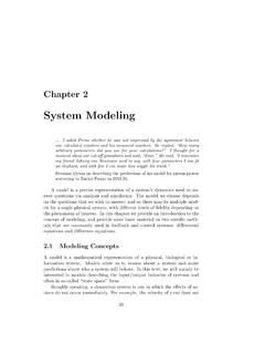
4 The controller parametersare proportional gainK, integral timeTi, and derivative , proportional and derivative part can be interpreted as controlactions based on the past, the present and the future as is illustratedin Figure The derivative part can also be interpreted as predictionby linear extrapolation as is illustrated in Figure The action of thedifferent terms can be illustrated by the following figures which show theresponse to step changes in the reference value in a typical of Proportional, Integral and Derivative ActionProportional Control is illustrated in Figure The controller is [andTd 0. The figure shows that there is alwaysa steady state error in proportional Control .]
5 The error will decrease withincreasing gain, but the tendency towards oscillation will also illustrates the effects of adding integral. It follows the strength of integral action increases with decreasing integral timeTi. The figure shows that the steady state error disappears when integralaction is used. Compare with the discussion of the magic of integralaction in Section Section The tendency for oscillation also increaseswith decreasingTi. The properties of derivative action are illustrated inFigure illustrates the effects of adding derivative action. The pa-rametersKandTiare chosen so that the closed-loop system is increases with increasing derivative time, but decreases againwhen derivative time becomes too large.
6 Recall that derivative action canbe interpreted as providing prediction by linear extrapolation over thetimeTd. Using this interpretation it is easy to understand that derivativeaction does not help if the prediction timeTdis too large. In Figure period of oscillation is about 6 s for the system without derivative217 Chapter 6. PID Control051015200105101520 22K 5K 2K 1K 5K 2K 1 Figure of a closed-loop system with proportional Control . The pro-cess transfer function isPDsE 1/Ds 1Ti 2Ti 5Ti [Ti 1Ti 2Ti 5Ti [Figure of a closed-loop system with proportional and integral con-trol. The process transfer function isPDsE 1/Ds 1E3, and the controller gain isK Derivative actions ceases to be effective whenTdis larger thana1sDone sixth of the periodE.]]
7 Also notice that the period of oscillationincreases when derivative time is PerspectiveThere is much more to PID than is revealed A faithful imple-mentation of the equation will actually not result in a good controller . Toobtain a good PID controller it is also necessary to Filtering and Set Point Weighting051015200105101520 22Td of a closed-loop system with proportional, integral andderivative Control . The process transfer function isPDsE 1/Ds 1E3, the controllergain isK 3, and the integral time isTi 2. Noise filtering and high frequency roll-off Set point weighting and 2 DOF Windup Tuning Computer implementationIn the case of the PID controller these issues emerged organically as thetechnology developed but they are actually important in the implemen-tation of all controllers.
8 Many of these questions are closely related tofundamental properties of feedback, some of them have been discussedearlier in the Filtering and Set Point WeightingFilteringDifferentiation is always sensitive to noise. This is clearly seen from thetransfer functionGDsE sof a differentiator which goes to infinity forlarges. The following example is also 6. PID DIFFERENTIATION AMPLIFIES HIGH FREQUENCY NOISEC onsider the signalyDtE sint nDtE sint ansin ntwhere the noise is sinusoidal noise with frequency . The derivative ofthe signal isdyDtEdt cost nDtE cost an cos ntThe signal to noise ratio for the original signal is 1/anbut the signal tonoise ratio of the differentiated signal is /an.
9 This ratio can be arbitrarilyhigh if is a practical controller with derivative action it is therefor necessary tolimit the high frequency gain of the derivative term. This can be done byimplementing the derivative term asD sKTd1 ofD sTdY. The approximation given be interpretedas the ideal derivativesTdfiltered by a first-order system with the timeconstantTd/N. The approximation acts as a derivative for low-frequencysignal components. The gain, however, is limited toKN. This means thathigh-frequency measurement noise is amplified at most by a values ofNare 8 to limitation of the high-frequency gainThe transfer function from measurementyto controller outputuof a PIDcontroller with the approximate derivative isCDsE K 1 1sTi sTd1 sTd/N This controller has constant gainlims0[CDsE KD1 NEat high frequencies.]
10 It follows from the discussion on robustness againstprocess variations in Section that it is highly desirable to roll-off Filtering and Set Point Weightingcontroller gain at high frequencies. This can be achieved by additionallow pass filtering of the Control signal byFDsE 1D1 sTfEnwhereTfis the filter time constant andnis the order of the filter. Thechoice ofTfis a compromise between filtering capacity and value ofTfcan be coupled to the controller time constants in thesame way as for the derivative filter above. If the derivative time is used,Tf Td/Nis a suitable choice. If the controller is only PI,Tf Ti/Nmay be controller can also be implemented asCDsE K 1 1sTi sTd 1D1 structure has the advantage that we can develop the design meth-ods for an ideal PID controller and use an iterative design procedure.