Transcription of Pilot oPerated Flow Control valveS with analog ... - …
1 WHAT MOVES YOUR WORLDWHAT MOVES YOUR WORLDSERVO VALVESPILOT oPerated FLOW Control valveS WITH analog INTERFACE78 SERIES STANDARD AND HIGH RESPONSE VERSIONSHIGH PERFORMANCE, FLOW Control IN A SIMPLE, DEPENDABLE, RUGGED AND LONG-LIFE DESIGNRev. N, July 201878 SERIES FLOW Control SERVO VALVES2 Rev. N, July 2018 INTRODUCTIONMoog 78 Series Flow Control Servo valveS 2 INTRODUCTIONMoog 78 Series Flow Control Servo valveS Whenever the highest levels of motion Control performance and design flexibility are required, you ll find moog expertise at work. Through collaboration, creativity and world-class technological solutions, we help you overcome your toughest engineering obstacles. Enhance your machine s performance. And help take your thinking further than you ever thought OF CONTENTSThis catalog is for users with technical knowledge.
2 To ensure all necessary characteristics for function and safety of the system, the user has to check the suitability of the products described herein. The products described herein are subject to change without notice. In case of doubt, please contact moog . moog is a registered trademark of moog Inc. and its subsidiaries. All trademarks as indicated herein are the property of moog Inc. and its subsidiaries. For the full disclaimer refer to the most current information, visit or contact your local moog ..2 Product Overview ..3 Features and Benefits ..4 Description of operation ..5 TECHNICAL DATA ..678 Series - Standard Response Servo valveS ..678 Series - High Response Servo valveS ..8 Electrical data ..10 Installation Drawings and Null Adjust Instructions ..1178 Series Hole Pattern for Mounting Surface ..13 BACKGROUND ..14 Null Flow Adjustment.
3 14 Flow calculation ..15 Null Cut Options ..15 Related Products ..16 Routine Maintenance Guidelines ..17 About moog ..18 ORDERING INFORMATION ..20 Accessories and Spare Parts ..20 Ordering Code ..213 Rev. N, July 2018 INTRODUCTIONMoog 78 Series Flow Control Servo ValvesPrOduCT OvErviEw3 INTRODUCTIONMoog 78 Series Flow Control Servo ValvesPrOduCT OvErviEwTIISI ntrinsically safe valve versions are available for use in hazardous locations. Specific models are certified to FM, ATEX, CSA and TIIS standards. Contact moog for response valveS with spoolHigh response valveS with spoolValve design2-stage, with spool and bushing and dry torque motorMounting patternUnique to 78 SeriesMaximum operating pressure to ports P, T, A, B210 bar (3000 psi)Maximum flow208 l/min ( gpm)156 l/min ( gpm) Pilot stageNozzle FlapperRated flow at pN 35 bar/spool land (500 psi/spool land)75 l/min (20 gpm)115 l/min (30 gpm)150 l/min (40 gpm)75 l/min (20 gpm)115 l/min (30 gpm)Step response time for 0 to 100 % stroke30 ms40 ms15 ms20 msThe 78 series is part of the moog family of Mechanical Feedback (MFB) Servo valveS .
4 They are throttle valveS for 3 and 4 way applications. This series has a high performance, two-stage design that covers a range of rated flows from 75 to 150 l/min (20 to 40 gpm) at 35 bar (500 psi) valve drop per spool land. These valveS are intended for position, speed, pressure or force Control applications that require high dynamic response. The 78 series MFB offers high dynamics, high resolution and low hysteresis due to its low friction double nozzle Pilot design is simple and rugged for dependable, long life operation. The output stage is a closed center, 4 way sliding spool. The Pilot stage is comprised of a symmetrical, double nozzle dry torque motor. The 2nd stage spool position is controlled by a carbide tipped feedback wire. The carbide ball on the end of the feedback wire is a mandatory design requirement that ensures high accuracy, reliable operation and long service life.
5 All of our servo valveS are known for high accuracy and reliable operation even in the harshest industrial family of valveS is considered a flow Control servo valve with an analog interface, but does not contain integrated electronics. The options in this series include standard and high response, special null (spool) cuts, seal materials and connectors. Intrinsically safe and flameproof designs for use in hazardous environments are also available with specific models certified to FM, ATEX, CSA and TIIS (Asian) of our valveS are backed by moog Global Support, our promise to provide world-class repair and maintenance services delivered by our trained technicians. Each valve possesses a long life design , controlled by proven servo valve technology that has an outstanding history of 60 years of meeting the motion Control needs of our customers. All of this makes moog servo valveS the best choice for your hydraulic motion Control N, July 2018 INTRODUCTIONMoog 78 Series Flow Control Servo ValvesFEATurES ANd BENEFiTS4 INTRODUCTIONMoog 78 Series Flow Control Servo ValvesFEATurES ANd BENEFiTSFeaturesBenefits100% factory tested to ensure critical specification performanceEnsures smooth and easy startup, reduces downtime and insures long life in critical industrial applications2 Stage DesignEnables high machine performance, faster cycle times and greater accuracy - all resulting in higher productivityDual Coil torque motorRedundancy for high reliabilityDual Precision Nozzles in Torque MotorPrecision flow Control and predictabilityDry torque motor designEliminates potential contamination issues in the air gaps of the torque motor that could cause machine downtimeHardened 440C Bushing and SpoolProvides for high life.
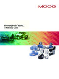
6 Wear resistance when used in the harsh environments; provides for low sliding friction during useEmergency failsafe positioningMost valveS are set up to return to a failsafe position when the command signal is interrupted or eliminatedField replaceable Pilot stage filterEnables preventive maintenance in the field, saving precious machine downtime and service costsExternal null bias adjustmentEnables technicians to manually adjust the null bias of the valve to adapt to the conditions of the machine (see section on null flow adjustment Page 14). This feature provides a simple adjustment to machine performance without the need to adjust a 78 Series is proven technology that performs reliably in machines where high performance, stability and accuracy are required. moog s Mechanical Feedback valveS are designed to provide high reliability and long service life. The current technology reflects over 60 years of experience of servo Control in some of the world s most demanding N, July 2018 INTRODUCTIONMoog 78 Series Flow Control Servo ValvesdESCriPTiON OF OPErATiON5 INTRODUCTIONMoog 78 Series Flow Control Servo ValvesdESCriPTiON OF OPErATiONPBTAS poolFeedback WireFlapperLower PolepieceUpper PolepieceInlet OrificeFlexure TubeCoilArmatureConnectorElectro-hydraul ic Servo valve Cut-awayThe 78 Series Flow Control Servo Valve consists of a polarized electrical torque motor and two stages of hydraulic power amplification.
7 The torque motor armature extends into the air gaps of the magnetic flux circuit and is supported in this position by a flexure tube. The flexure tube acts as a seal between the electromagnetic and hydraulic sections of the valve. The 2 torque motor coils surround the armature, one on each side of the flexure flapper of the first stage hydraulic amplifier is rigidly attached to the midpoint of the armature. The flapper extends through the flexure tube and passes between 2 nozzles, creating two variable orifices between the nozzle tips and the flapper. The Pilot pressure is controlled by the flapper/nozzle variable orifice and is in turn fed to the end areas of the second stage spool. This action creates a differential pressure from one end of the spool to the other and results in spool displacement. The spool displacement causes a force in the feedback wire which opposes the original input signal torque.
8 Spool movement continues until the feedback wire force equals the input signal second stage is a conventional four-way spool design in which output flow from the valve, at a fixed valve pressure drop, is proportional to spool displacement from the null position. A cantilever feedback spring is fixed to the flapper and engages a slot at the center of the spool. Displacement of the spool deflects the feedback spring which creates a force on the armature/flapper signal induces a magnetic charge in the armature and causes a deflection of the armature and flapper. This assembly pivots about the flexure tube and increases the size of one nozzle orifice and decreases the size of the N, July 2018 TECHNICAL DATAMoog 78 Series Flow Control Servo Valves78 SEriES - STANdArd rESPONSE SErvO vALvES6 TECHNICAL DATAMoog 78 Series Flow Control Servo Valves78 SEriES - STANdArd rESPONSE SErvO vALvESSample deviation of rated flow 10 %Step response time for 0 to 100 % stroke30 ms30 ms40 %Hysteresis< %Null shift at T = 38 C (100 F)< %General Technical DataHydraulic DataStatic and Dynamic DataMaximum operating pressure to ports P, T, A, B210 bar (3,000 psi)Rated flow at pN 35 bar/spool land (500 psi/spool land)75 l/min (20 gpm)115 l/min (30 gpm)150 l/min (40 gpm)Maximum flow208 l/min ( gpm)Null adjust authorityGreater than 10 % of rated flowHydraulic fluidHydraulic oil as per DIN 51524 parts 1 to 3 and ISO 11158.
9 Other fluids on range-40 to +135 C (-40 to +275 F)Recommended viscosity range 10 to 85 mm2/s (cSt)Maximum permissible viscosity range5 to 1250 mm2/s (cSt)Recommended cleanliness class as per ISO 4406 For functional safety17/14/11 For longer service life15/13/10 Recommended filter ratingFor functional safety 10 = 75 (10 m absolute)For longer life 5 = 75 (5 m absolute)Valve design2-stage, with spool and bushing and dry torque motorPilot stageNozzle FlapperMounting patternUnique to 78 SeriesInstallation positionAny orientation, fixed or kg ( lb)Storage temperature range-40 to +60 C (-40 to +140 F)Ambient temperature range-40 to +135 C (-40 to +275 F)Vibration resistance30 g, 3 axis, 10 Hz to 2 kHzShock resistance30 g, 3 axisSeal materialFluorocarbon (FKM) 85 Shore D Others upon request7 Rev. N, July 2018 TECHNICAL DATAMoog 78 Series Flow Control Servo Valves78 SEriES - STANdArd rESPONSE SErvO valveS 7 TECHNICAL DATAMoog 78 Series Flow Control Servo Valves78 SEriES - STANdArd rESPONSE SErvO valveS 12438040120-4+2-8-16-120051010050-20 DecibalsFrequency (Hz)Phase Lag (Degrees)1202040608010020405030100 Stroke (% of Rated Signal)Time (ms)12340800051010050-4+2-8-16-12-204120 Phase Lag (Degrees)Frequency (Hz)0 DecibalsNote.
10 Measured with 210 bar (3,000 psi), DTE -24 fluid at +38 C (+100 F)02030101051525203035124050 Time (ms)Stroke (% of Rated Signal)Reduced Amplitude Step Response33 % stepPlot 1 = 75/115 l/min (20/30 gpm) Plot 2 = 150 l/min (40 gpm)Standard Frequency Response75/115 l/min (20/30 gpm)Plot 1 & 3 = 40 % rated signalPlot 2 & 4 = 100 % rated signalFull Amplitude Step Response100 % stepPlot 1 = 75/115 l/min (20/30 gpm) Plot 2 = 150 l/min (40 gpm)Standard Frequency Response154 l/min (40 gpm)Plot 1 & 3 = 40 % rated signalPlot 2 & 4 = 100 % rated signal8 Rev. N, July 2018 TECHNICAL DATAMoog 78 Series Flow Control Servo Valves78 SEriES - HigH rESPONSE SErvO vALvES8 TECHNICAL DATAMoog 78 Series Flow Control Servo Valves78 SEriES - HigH rESPONSE SErvO vALvESGeneral Technical DataHydraulic DataStatic and Dynamic DataMaximum operating pressure to ports P, T, A, B210 bar (3,000 psi)Rated flow at pN 35 bar/spool land (500 psi/spool land)75 l/min (20 gpm)115 l/min (30 gpm)Maximum flow156 l/min ( gpm)Null adjust authorityGreater than 10 % of rated flowHydraulic fluidHydraulic oil as per DIN 51524 parts 1 to 3 and ISO 11158.