Transcription of Pipe Sizes For Water Distribution System Design
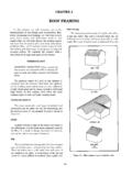
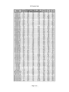
1 D-1 Appendix DPipe Sizes For Water Distribution System DesignD-1. This appendix contains information to help determine pipe Sizes whendesigning a Water Distribution System . UseTable D-1 and Tables D-2 throughD-4, pages D-3 through D-6to determine pipe D-1. Capacities of Galvanized-Steel/Iron pipe (in GPM)Length of pipe (in Feet)Pressure atSource (psi)204060801001201401601802003/8 Inch105332222095433322223010654433332408 6544433350976544333609766554447010876655 4480877655541/2 Inch101085543333320141086655444301812108 8766554020141110108776650161311119877760 18141212109987701513121110988803/4 Inch102214121088766620302218141212111010 8303826221816141312121040302421191716161 5135034282421191817161560383126232120191 817703429252322211918803630272423222120F M pipe Sizes For Water Distribution System DesignPressure atSource (psi)204060801001201401601802001 Inch104028221816151413121120554032272422 2019181630705040343027252322204080584540 3532292725245065574540363331292760705850 4440363432307076635445424037343280655747 43393735331 1/4 Inch108055453735302725262420110806555504 5413836343010080706056514745424095807265 6056525050107928274686360556010290817570 6562709788827469678010595877974721 1/2 Inch101209070605550454040352017013010090 7570656055553016013011010090807570654017 0150130110100909080805017014013012011010 0909060160140130120110100100701701501401 30120110100801601501401301201102 Inch102401601301101009090808070203002402 0016015014013012011010030300240200180160 1501401401304038024022020018016016015050 2802402202002001801606028024022020020018 07030026024022022020080280260240220220 Table D-1.
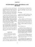
2 Capacities of Galvanized-Steel/Iron pipe (in GPM) (Continued)Length of pipe (in Feet)FM Sizes For Water Distribution System Design D-3 Table D-2. Capacities of Copper Tubing and Plastic pipe (in GPM)Length of pipe (in Feet)Pressure atSource (psi)204060801001201401601802001/2 Inch108543322222201286554433330151087655 4444017129876655450141098766556015121098 77667013111098776801412101088775/8 Inch101287655443320181210976655530221612 1099876640261814121010988750221614121110 9986024181614131211109702018151413121110 8022191615141312113/4 Inch102014101088666520302016141210101088 3036262017151413111084030242018161514131 2503428242018161614146036302622201818161 67032282422201818168036302624222018181 Inch105030242018161414121220704536302624 2220181830805545383430282624224065554540 3632302826507560504540363432306080665550 4540383634707060555045403836808065605050 454040FM pipe Sizes For Water Distribution System DesignPressure atSource (psi)204060801001201401601802001 1/4 Inch108055423732302725222220110806555474 2403535323010580706055504544404011095807 0656055504750110908070656057556010590807 5706560701101009080757065801059585807570 1 1/2 Inch101309070605045404035352017013010090 7570656055503017013011010090807570654015 5130115105958880775017015013012010810090 8860165145130120110105987017016014213012 2113106801701551401301221152 Inch102801801501451101009085807020320280 2201901651601401251201103032028024021018 0170160150140403202802402202001901751605 0320280250230210200190603002802602402202 007032030028026024023080320300280260240 Table D-2.
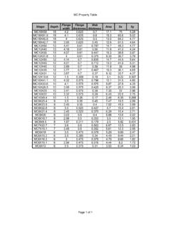
3 Capacities of Copper Tubing and Plastic pipe (in GPM) (Continued)Length of pipe (in Feet)FM Sizes For Water Distribution System Design D-5 Table D-3. Allowance for Equivalent Length of pipe for Friction Loss(Valve and Threaded Fittings)Diameterof Fitting(in Inches)90 StandardElbow,Foot45 StandardElbow,Foot90 SideT, FootCouplingof StraightRun of T,FootGateValve,FootGlobeValve,FootAngle Valve,Foot3 1 1 1 1 FM pipe Sizes For Water Distribution System DesignD-2. Refer toFigures D-1 through D-5, pages D-7 through D-11,todesignand draw a Water service line. These figures can also be used to determinepipe Use the following steps andFigure D-1to determine the size of the pipe ,the velocity, and the friction loss from Point A to Point B:Step the number along the bottom of the the flow rate in GPM demand along the left side of thechart, using the GPM demand from Step to the right from the GPM scale and up from the D-4.
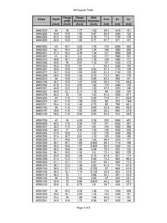
4 Head Loss, Equivalent Length of pipe (in Feet)OrdinaryEntranceSudden EnlargementSudden Contractiond1D4d1D2d3D4d1D4d1D2d3D4 size ofPiped(in inches)1 1 1 1 1 1 Sizes For Water Distribution System Design D-7 Step the point at which these two values intersect. From thispoint, read left and stop at the first pipe size selection line. This is the sizeof pipe D-1. Friction Loss Using a Fairly Smooth "1/2"3/4"1"11/4"11/2"2"21/2"8fpsline6fps linepsilossPF demandPipe sizeselected:fps:loss inpsi:14FM pipe Sizes For Water Distribution System DesignFigure D-2. Friction Loss, Rough 9020406080 80 10010,0008,0006,0004,0003,0002,000600800 1,0002003004005005,000203040234681016080 10050510,0008,0006,0004,0003,0002,000200 3004006008001,0005002030406080100505,000 Head (in psi per 100 feet)Flow(inGPM)RoughHead (in psi per 100 feet)Pipediameter(ininches)Recommendedve locities(2to10fps)Velocity(infps)2346810 1512106543211/213/41/23/8123456810152030 Flow(inGPM)FM Sizes For Water Distribution System Design D-9 Figure D-3.
5 Friction Loss, Fairly Rough rough3579246810305070 9020406080 10010,0008,0006,0004,0003,0002,000200300 4006008001,0005005,000203040608010050 Flow(inGPM) 70 90 Head (in psi per 100 feet)Head (in psi per 100 feet)10,0006,0004,0003,0002,0008,0005,00 06008001,0002030406080100200300400234681 01500505 Pipediameter(ininches)Recommendedvelocit ies(2to10fps)Velocity(infps)12108654311/ 213/41/23/8403020151086254321 Flow(inGPM)FM pipe Sizes For Water Distribution System DesignFigure D-4. Friction Loss, Smooth 93050 70 10204060 80 10010,0008,0006,0004,0003,0002,000123468 1020304060801002003004006008001,00010,00 08,0006,0004,0003,0002,0006008001,000203 040608010020030040023468101 Head (in psi per 100 feet)Flow(inGPM)Head (in psi per 100 feet)Copper tube, smoothType MType LType KPipediameter(ininches)Recommendedveloci ties(2to10fps)Velocity(infps)12345681015 2030406543211/213/41/23/8 Flow(inGPM)FM Sizes For Water Distribution System Design D-11 Figure D-5.
6 Friction Loss, Fairly Smooth 80 10010,0008,0006,0004,0003,0002,000200300 4006008001,00050012346810203040608010050 510,0008,0006,0004,0003,0002,0006008001, 000 Fairly smooth203040234681016080100200300400505 Head (in psi per 100 feet)Head (in psi per 100 Flow(inGPM)Pipediameter(ininches)Recomme ndedvelocities(2to10fps)Velocity(infps)1 21086543211/23/411/23/840403020151085643 12 Head (in psi per 100 feet)Flow(inGPM)E-1 Appendix EDistribution Systems Design ProceduresDESIGN PROCEDURESBASIC CONCEPTSE-1. Water weighs pounds per cubic ft (lb/ft3)PressureE-2. Pressure (P) is an expression, in psi (lb/in2), of the total gravitationalforce (lb) exerted at the base of an imaginary 1-inch square (in2)columnofwater thus psi of any column height or head (H) in feet (Figure E-1).So, for example, for a 10-foot column, or head of Water (H) the pressure would be:Figure E-1. Water PressureP(lbs/in2) (ft) P = ;=P(lbs/in2) (ft) P = (10) = psi;=1 cubic footOne column of Water weighsapproximately = 12 12 FM Distribution Systems Design ProceduresHeadE-3.)
7 Conversely, "head" is another way to express the same total forceexerted by the same column of Water , expressed in E-2:so(Note: for any other liquid, the constant of would change with anychange in density).So, for example, for a pressure of psi, the head would be:H = or ( ) = 10 foot headAnother way to express this is "a 10-foot head of pressure" which is Head. Static head is the height of a fluid at rest (no flow) (FigureE-2). Head. Dynamic head is static head minus the friction loss ofa flowing liquid, expressed in feet (Figure E-3). It is also known as free-watersurface (FWS) Use the following definitions to identify equations:Figure E-2. Static HeadP(psi)= (ft)Hft()Ppsi() P = pressure in psi==StaticliquidlevelStaticheadDynamic headStatic head - Friction loss=FM Systems Design Procedures E-3 PfallowableThe maximum pressure that can be lost from all sources offriction without falling below the required service-connectionpressure.
8 (Minimum service-connection pressure in the TO is 20 psi.) PfactualThe pressure loss from all sources of friction in a pipe segment. PFallowableThe allowable pressure loss in a 100-foot section. PFactualThe actual pressure loss in a 100-foot section. Equivalent Length (EL). The length of a fitting or valve expressed infeet of straight pipe that produces the same amount of friction loss. Pressure at Service Connection (PSC). The actual pressure that will beprovided to the user (building or facility).DYNAMIC Water Distribution System DESIGNE-7. Dynamic Water Distribution systems are designed using the proceduresbelow. When working the two examples that follow, refer back to theprocedures PROCEDURESE-8. Use the following steps to perform Design procedures:Step the quantity (Q) of the flow rate, in each = height ( )Figure E-3. Relation of Static and Dynamic HeadsStaticliquidlevelStaticheadFriction headlossDynamicheadPfallowableHE1E2 ()required pressure =where Pfallowableallowable pressure loss, in psi=FM Distribution Systems Design ProceduresE1 = higher elevation, in feetE2 = lower elevation, in feetStep the pipe length (in feet).
9 Step a 100-foot section of total System length is in the fluid's actual velocity, which should be between 2 and 10 fps, andfindPFactual(fromFigures D-1 to D-5, pages D-7 through D-11).Step ,andPFactual(fromTables D-3 and D-4, pages D-5 through D-6).Step actual pressure loss from all sources, in psiPFactual= actual pressure loss in a 100-foot pipe section, in psiSystem length is in the equivalent pipe length (EL) for fittings. Go back toStep 4and recalculate PFallowable. If the pipe size changes in the appropriatefriction loss table (Figure D-1 through D-5, pages D-7 through D-11), thenfind the new velocity and PFactualfromFigures D-1 through if there is 1,000 feet or more between surface (FWS) the pressure at the service System length---------------------------------- -----------x100 where PFallowableallowable pressure loss in a 100-foot pipe section, in psiPfallowableallowable pressure loss, in psiPfactualPFactual100 --------------------=x System lengthwhere FWSEBTH(Pfactual) =where FWSfree Water surface, in feet=EBTelevation at bottom of the tank, in feet=Hheight or head (constant )=Pfactualactual pressure factor (from Step 6), in psi=PSCHEBT(ESC)-Pfactual =FM Systems Design Procedures E-5 EXAMPLE - Water LINE Design 1E-9.
10 Use the following steps as an example to Design a Water line:Step the required Q from the tank to the pipe length. pipe length given is 1,300 feet (FigureE-4).Figure E-4. Water Line, Design 1where PSCpressure at the servicice connection, in psi=Hheight ( )=EBTelevation at bottom of the tank, in feet=ESCelevation at the service connection, in feet=Q230 GPM (Figure E-4)=PfallowableHE1(E2)- required pressure = 13570)-20 ( psi=+145 +135 Elevation = 70 Pressure = 20 psiQ=230 GPML egend: Q = Quantity of flow rateTotal length of the pipe from the bottomof the tank to the building is 1,300 Distribution Systems Design ProceduresStep Pfallowablein a 100-foot a 6-inch diameter pipe and a velocity of fps(intersection of selected pipe and Q). SeeFigure D-3, page PfactualStep the EL. EL is feet (refer topage E-4, Step 7).Step the pressure at the service - Water LINE Design 2E-10. Use the following steps as an example to Design a Water line:Step Q from Tank to A.