Transcription of POINT I/O Common Terminal Module and Voltage …
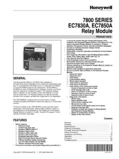
1 Installation Instructions POINT I/O Common Terminal Module and Voltage Terminal Module Catalog No. 1734-CTM, Series C, and 1734-VTM, Series C. Module Locking Mechanism Insertable I/O Module Module Wiring Diagram DIN Rail Locking RTB Removable Handle Screw (orange). Mechanical keying Removable Terminal (orange) Block (RTB). Interlocking Side Pieces 31538-M. Mounting Base The Wiring Base Assembly consists of Mounting Base, 1734-MB, and Removable Terminal Block, 1734-RTB or 1734-RTBS. Publication 1734-IN024A-EN-E - March 2005. 2 POINT I/O Common Terminal Module and Voltage Terminal Module Important User Information Solid state equipment has operational characteristics differing from those of electromechanical equipment. Safety Guidelines for the Application, Installation and Maintenance of Solid State Controls (Publication available from your local Rockwell Automation sales office or online at ) describes some important differences between solid state equipment and hard-wired electromechanical devices.
2 Because of this difference, and also because of the wide variety of uses for solid state equipment, all persons responsible for applying this equipment must satisfy themselves that each intended application of this equipment is acceptable. In no event will Rockwell Automation, Inc. be responsible or liable for indirect or consequential damages resulting from the use or application of this equipment. The examples and diagrams in this manual are included solely for illustrative purposes. Because of the many variables and requirements associated with any particular installation, Rockwell Automation, Inc. cannot assume responsibility or liability for actual use based on the examples and diagrams. No patent liability is assumed by Rockwell Automation, Inc. with respect to use of information, circuits, equipment, or software described in this manual. Reproduction of the contents of this manual, in whole or in part, without written permission of Rockwell Automation, Inc.
3 , is prohibited. Throughout this manual, when necessary, we use notes to make you aware of safety considerations. WARNING Identifies information about practices or circumstances that can cause an explosion in a hazardous environment, which may lead to personal injury or death, property damage, or economic loss. IMPORTANT. Identifies information that is critical for successful application and understanding of the product. ATTENTION Identifies information about practices or circumstances that can lead to personal injury or death, property damage, or economic loss. Attentions help you: identify a hazard avoid a hazard recognize the consequence SHOCK HAZARD Labels may be located on or inside the equipment ( , drive or motor) to alert people that dangerous Voltage may be present. BURN HAZARD Labels may be located on or inside the equipment ( , drive or motor) to alert people that surfaces may be dangerous temperatures. Publication 1734-IN024A-EN-E - March 2005.
4 POINT I/O Common Terminal Module and Voltage Terminal Module 3. WARNING Environment and Enclosure This equipment is intended for use in a Pollution Degree 2 industrial environment, in overvoltage Category II. applications (as defined in IEC publication 60664-1), at altitudes up to 2000 meters without derating. This equipment is considered Group 1, Class A industrial equipment according to IEC/CISPR Publication 11. Without appropriate precautions, there may be potential difficulties ensuring electromagnetic compatibility in other environments due to conducted as well as radiated disturbance. This equipment is supplied as open type equipment. It must be mounted within an enclosure that is suitably designed for those specific environmental conditions that will be present and appropriately designed to prevent personal injury resulting from accessibility to live parts. The interior of the enclosure must be accessible only by the use of a tool. Subsequent sections of this publication may contain additional information regarding specific enclosure type ratings that are required to comply with certain product safety certifications.
5 See NEMA Standards publication 250 and IEC publication 60529, as applicable, for explanations of the degrees of protection provided by different types of enclosure. Also, see the appropriate sections in this publication, as well as the Allen-Bradley publication ( Industrial Automation Wiring and Grounding Guidelines ), for additional installation requirements pertaining to this equipment. Publication 1734-IN024A-EN-E - March 2005. 4 POINT I/O Common Terminal Module and Voltage Terminal Module WARNING Explosion Hazard Do not disconnect equipment unless power has been removed or the area is known to be nonhazardous. Do not disconnect connections to this equipment unless power has been removed or the area is known to be nonhazardous. Secure any external connections that mate to this equipment by using screws, sliding latches, threaded connectors, or other means provided with this product. Substitution of components may impair suitability for Class I, Division 2.
6 If this product contains batteries, they must only be changed in an area known to be nonhazardous. About the Modules The POINT I/O Common Terminal Module and Voltage Terminal Module provide expansion of the termination capability of POINT . I/O. The modules support higher density (8 channel) POINT I/O. modules and management of wiring of field devices to the POINT . I/O solution. Publication 1734-IN024A-EN-E - March 2005. POINT I/O Common Terminal Module and Voltage Terminal Module 5. Install the Mounting Base To install the mounting base on the DIN rail, proceed as follows. 1. Position the mounting base vertically above the installed units (adapter, power supply, or existing Module ). 2. Slide the mounting base down so that the interlocking side pieces to engage the adjacent Module or adapter. 3. Press firmly to seat the mounting base on the DIN rail. The mounting base snaps into place. Install the Module Install the Module before or after mounting base installation.
7 Be sure to correctly key the mounting base before installing the Module into the mounting base. In addition, be sure to position the mounting base locking screw horizontal referenced to the base. WARNING When you insert or remove the Module while backplane power is on, an electrical arc can occur. This could cause an explosion in hazardous location installations. Be sure that power is removed or the area is nonhazardous before proceeding. Repeated electrical arcing causes excessive wear to contacts on both the Module and its mating connector. Worn contacts may create electrical resistance that can affect Module operation. 1. Using a bladed screwdriver, rotate the keyswitch on the mounting base clockwise until the number required for the type of Module you are installing aligns with the notch in the base. Publication 1734-IN024A-EN-E - March 2005. 6 POINT I/O Common Terminal Module and Voltage Terminal Module 2. Make certain the DIN rail locking screw is in the horizontal position.
8 You cannot insert the Module if the locking mechanism is unlocked. 3. Insert the Module straight down into the mounting base and press to secure. The Module locks into place. Install the Removable Terminal Block (RTB). You will find the RTB supplied with the wiring base assembly. To remove, pull up on the RTB handle. You can now remove the mounting base and replace as necessary without removing any of the wiring. To reinsert the RTB, proceed as follows. 1. Insert the end opposite the handle into the base unit. This end has a curved section that engages with the wiring base. 2. Rotate the Terminal block into the wiring base until it locks itself in place. 3. If an I/O Module is installed, snap the RTB handle into place on the Module . Publication 1734-IN024A-EN-E - March 2005. POINT I/O Common Terminal Module and Voltage Terminal Module 7. Remove a Mounting Base To remove a mounting base, you must remove any installed Module , and the Module installed in the base to the right.
9 Remove the removable Terminal block (if wired). 1. Unlatch the RTB handle on the I/O Module . 2. Pull on the RTB handle to remove the removable Terminal block. 3. Press on the Module lock on the top of the Module . 4. Pull on the I/O Module to remove from the base. WARNING When you insert or remove the Module while backplane power is on, an electrical arc can occur. This could cause an explosion in hazardous location installations. Be sure that power is removed or the area is nonhazardous before proceeding. Repeated electrical arcing causes excessive wear to contacts on both the Module and its mating connector. Worn contacts may create electrical resistance that can affect Module operation. 5. Repeat steps 1, 2, 3, and 4 for the Module to the right. 6. Use a small-bladed screwdriver to rotate the orange base locking screw to a vertical position. This releases the locking mechanism. 7. Lift straight up to remove. Publication 1734-IN024A-EN-E - March 2005.
10 8 POINT I/O Common Terminal Module and Voltage Terminal Module Wire the Modules 1734-VTM 1734-CTM. 0. 0. 1. 1. 1734. 1734 CTM. VTM. Voltage Out Voltage Out Common Common Voltage Out Voltage Out Common Common Voltage Out Voltage Out Common Common Voltage Out Voltage Out Common Common Voltage Out = 0 to 7 Common = 0 to 7. 43929. Publication 1734-IN024A-EN-E - March 2005. POINT I/O Common Terminal Module and Voltage Terminal Module 9. Sink Input Wiring 1734-CTM. 1734-IB8 1734-VTM. 2-wire 0 1. 0 1 0 1. C C. Prox V V. In 0 In 1. 2 3. 2 3. 2 3 C C. V V. In 2 In 3. 4 5. 4 5. 4 5 C C. V V. In 4 In 5. 3-wire 6 7. 6 7. 6 7 C C. Prox V V. In 6 In 7. V = Voltage Out C = Common 43927. Publication 1734-IN024A-EN-E - March 2005. 10 POINT I/O Common Terminal Module and Voltage Terminal Module Source Input Wiring 1734-CTM. 1734-IV8 1734-VTM. 2-wire 0 1. 0 1 0 1. Prox V V. C C. In 0 In 1. 2 3. 2 3 2 3. V V. In 2 In 3 C C. 4 5. 5 4 5. 4 V V. In 4 In 5 C C. 3-wire 6 7.