Transcription of Power Electronics - Philadelphia University
1 Power Electronics Single Phase Uncontrolled Half Wave Rectifiers 1 Dr. Firas Obeidat 2 Table of contents 1 Resistive Load 2 R-L Load 3 R-L Load with Freewheeling Diode 4 Half Wave Rectifier with a Capacitor Filter Dr. Firas Obeidat Faculty of Engineering Philadelphia University 3 Dr. Firas Obeidat Faculty of Engineering Philadelphia University Introduction A rectifier is an electrical device that converts alternating current (AC) to direct current (DC), which flows in only one direction. The process is known as rectification.
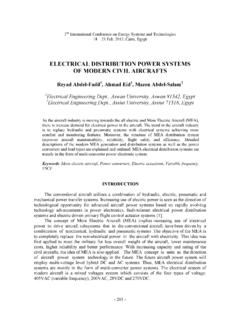
2 There are many applications for rectifiers. Some of them are: variable speed dc drives, battery chargers, DC Power supplies and Power supply for a specific application like electroplating. 4 Dr. Firas Obeidat Faculty of Engineering Philadelphia University Resistive Load A basic half-wave rectifier with a resistive load is shown in fig. a. The source is ac, and the objective is to create a load voltage that has a nonzero dc component. The diode is a basic electronic switch that allows current in one direction only.
3 For the positive half-cycle of the source in this circuit, the diode is on (forward-biased). Considering the diode to be ideal, the voltage across a forward-biased diode is zero and the current is positive. For the negative half-cycle of the source, the diode is reverse-biased, making the current zero. The voltage across the reverse-biased diode is the source voltage, which has a negative value. 5 Dr. Firas Obeidat Faculty of Engineering Philadelphia University Resistive Load The dc component Vo of the output voltage is the average value of a half-wave rectified sinusoid The dc component of the current for the purely resistive load is The rms values of Vo and Io can be written as Vdc= Idc= 6 Dr.
4 Firas Obeidat Faculty of Engineering Philadelphia University Resistive Load The Average output dc Power is = = 2 = 2 = 2 2 The rms output dc Power is = = 2 = 2 = 24 Example: For the shown half-wave rectifier, the source is a sinusoid of 120 Vrms at a frequency of 60 Hz. The load resistor is 5 . Determine (a) the average load current, (b) the dc and ac Power absorbed by the load and (c) the Power factor of the circuit. (a) 7 Dr. Firas Obeidat Faculty of Engineering Philadelphia University Resistive Load (b) (c) The rms current in the resistor is The Power factor is = 2 2 = 2 5= = 2 = = = = 17= 8 Dr.
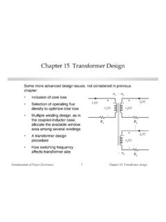
5 Firas Obeidat Faculty of Engineering Philadelphia University R-L Load Industrial loads typically contain inductance as well as resistance. As the source voltage goes through zero, becoming positive in the circuit of fig. a, the diode becomes forward-biased. The Kirchhoff voltage law equation that describes the current in the circuit for the forward-biased ideal diode is The dc component of the output voltage is = 2 0= 2 (1 ) The dc component of the output current is = 2 (1 ) (1) The solution of equation (1) can be obtained by expressing the current as the sum of the forced response and the natural response: 9 Dr.
6 Firas Obeidat Faculty of Engineering Philadelphia University R-L Load The forced response for this circuit is the current that exists after the natural response has decayed to zero. In this case, the forced response is the steady-state sinusoidal current that would exist in the circuit if the diode were not present. This steady-state current can be found from phasor analysis, resulting in Where The natural response is the transient that occurs when the load is energized. It is the solution to the homogeneous differential equation for the circuit without the source or diode.
7 10 Dr. Firas Obeidat Faculty of Engineering Philadelphia University R-L Load For this first-order circuit, the natural response has the form Adding the forced and natural responses gets the complete solution. Where = A= constant The constant A is evaluated by using the initial condition for current: t=0, i( t)=0. Using the initial condition and equation (2) to evaluate A yields (2) 11 Dr. Firas Obeidat Faculty of Engineering Philadelphia University R-L Load Substituting for A in equation (2) gives The final current equation can be written as The point when the current reaches zero in Eq.
8 (3-12) occurs when the diode turns off. The first positive value of t in equation (3) that results in zero current is called the extinction angle . (3) To find , substitute t= in equation (3) Which reduces to There is no closed-form solution for , and some numerical method is required. 12 R-L Load To summarize, the current in the half-wave rectifier circuit with RL load is expressed as = 2 0= 2 (1 ) The dc component of the output current is = = 2 (1 ) Or it can be found as 13 Dr.
9 Firas Obeidat Faculty of Engineering Philadelphia University R-L Load The rms value of Io can be written as Or it can be written as =12 ( )2 0= 24 ( 12 2 ) = = 2+( )2=1 2+( )2 24 ( 12 2 ) 14 Dr. Firas Obeidat Faculty of Engineering Philadelphia University R-L Load Example: For the RL half-wave rectifier, R=100 , L= H, =377 rad/s, and Vm=100 V. Determine (a) an expression for the current in this circuit, (b) the average current, (c) the rms current, (d) the Power absorbed by the RL load, and (e) the Power factor.
10 (a) Using a numerical root-finding program, is found to be rad, or 201o. (b) (A numerical integration program is recommended.) 15 Dr. Firas Obeidat Faculty of Engineering Philadelphia University R-L Load = = 2 1 =1002 1001 201= Io can be also found from (c) Irms can be also found from (d) (e) Note that the Power factor is not cos . =1 2+( )2 24 ( 12 2 )= ( 12 7)= A 16 Dr. Firas Obeidat Faculty of Engineering Philadelphia University R-L Load with Freewheeling Diode A freewheeling diode D2, can be connected across an RL load as shown in fig.