Transcription of Power MOSFET - Vishay
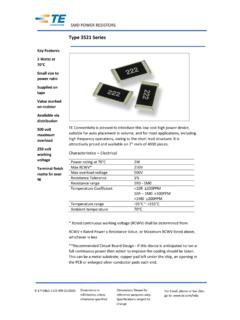
1 IRFR110, Siliconix S13-0171-Rev. F, 04-Feb-131 Document Number: 91265 For technical questions, contact: DOCUMENT IS SUBJECT TO CHANGE WITHOUT NOTICE. THE PRODUCTS DESCRIBED HEREIN AND THIS DOCUMENTARE SUBJECT TO SPECIFIC DISCLAIMERS, SET FORTH AT MOSFETFEATURES Dynamic dV/dt Rating Repetitive Avalanche Rated Surface Mount (IRFR110, SiHFR110) Available in Tape and Reel Fast Switching Ease of Paralleling Material categorization: For definitions ofcompliance please see DESCRIPTIONT hird generation Power MOSFETs from Vishay provide thedesigner with the best combination of fast switching,ruggedized device design, low on-resistance DPAK is designed for surface mounting using vaporphase, infrared, or wave soldering techniques.
2 Powerdissipation levels up to W are possible in typical surfacemount See device Repetitive rating; pulse width limited by maximum junction temperature (see fig. 11).b. VDD = 25 V, starting TJ = 25 C, L = mH, Rg = 25 , IAS = A (see fig. 12).c. ISD A, dI/dt 75 A/ s, VDD VDS, TJ 150 mm from When mounted on 1" square PCB (FR-4 or G-10 material). PRODUCT SUMMARYVDS (V)100 RDS(on) ( )VGS = 10 V (Max.) (nC) (nC) (nC) MOSFET GDSDPAK(TO-252)SDGORDERING INFORMATIONP ackageDPAK (TO-252)DPAK (TO-252)DPAK (TO-252)DPAK (TO-252)Lead (Pb)-free and Halogen-freeSiHFR110-GE3 SiHFR110 TRL-GE3 SiHFR110TR-GE3 SiHFR110 TRR-GE3 Lead (Pb)-freeIRFR110 PbF IRFR110 TRLPbFaIRFR110 TRPbFaIRFR110 TRRPbFaSiHFR110-E3 SiHFR110TL-E3aSiHFR110T-E3aSiHFR110TR-E3 aABSOLUTE MAXIMUM RATINGS (TC = 25 C, unless otherwise noted)
3 PARAMETER SYMBOLLIMITUNITD rain-Source Voltage VDS100V Gate-Source VoltageVGS 20 Continuous Drain CurrentVGS at 10 VTC = 25 C = 100 C Drain CurrentaIDM 17 Linear Derating C Linear Derating Factor (PCB Mount) Pulse Avalanche EnergybEAS 75mJ Repetitive Avalanche CurrentaIAR Repetitive Avalanche Maximum Power DissipationTC = 25 CPD25W Maximum Power Dissipation (PCB Mount)eTA = 25 Diode Recovery dV/dtcdV/dt Operating Junction and Storage Temperature RangeTJ, Tstg- 55 to + 150 C Soldering Recommendations (Peak Temperature)dfor 10 s260 IRFR110, Siliconix S13-0171-Rev.
4 F, 04-Feb-132 Document Number: 91265 For technical questions, contact: DOCUMENT IS SUBJECT TO CHANGE WITHOUT NOTICE. THE PRODUCTS DESCRIBED HEREIN AND THIS DOCUMENTARE SUBJECT TO SPECIFIC DISCLAIMERS, SET FORTH AT When mounted on 1" square PCB (FR-4 or G-10 material). Notesa. Repetitive rating; pulse width limited by maximum junction temperature (see fig. 11).b. Pulse width 300 s; duty cycle 2 %.THERMAL RESISTANCE RATINGSPARAMETER Junction-to-AmbientRthJA-110 C/WMaximum Junction-to-Ambient (PCB Mount)aRthJA-50 Maximum Junction-to-Case (Drain) (TJ = 25 C, unless otherwise noted)PARAMETER SYMBOLTEST CONDITIONS Breakdown Voltage VDS VGS = 0 V, ID = 250 A 100--V VDS Temperature Coefficient VDS/TJ Reference to 25 C, ID = 1 mA C Gate-Source Threshold Voltage VGS(th)
5 VDS = VGS, ID = 250 A Gate-Source Leakage IGSS VGS = 20 V-- 100nA Zero Gate Voltage Drain Current IDSS VDS = 100 V, VGS = 0 V --25 A VDS = 80 V, VGS = 0 V, TJ = 125 C --250 Drain-Source On-State Resistance RDS(on) VGS = 10 VID = Forward Transconductance gfsVDS = 50 V, ID = DynamicInput Capacitance Ciss VGS = 0 V, VDS = 25 V,f = MHz, see fig. 5 -180-pFOutput Capacitance Coss -80-Reverse Transfer Capacitance Crss -15-Total Gate Charge Qg VGS = 10 V ID = A, VDS = 80 V, see fig.
6 6 and Gate-Source Charge Qgs ChargeQgd Delay Time td(on) VDD = 50 V, ID = A, Rg = 24 , RD = , see fig. Timetr -16-Turn-Off Delay Time td(off) -15-Fall Time tf Drain Inductance LD Between lead,6 mm ( ") from package and center of die contact Internal Source Body Diode CharacteristicsContinuous Source-Drain Diode Current ISMOSFET symbolshowing the integral reversep - n junction Diode Forward CurrentaISM--17 Body Diode VoltageVSDTJ = 25 C, IS = A, VGS = 0 Diode Reverse Recovery TimetrrTJ = 25 C, IF = A, dI/dt = 100 A/ sb-100200nsBody Diode Reverse Recovery CForward Turn-On TimetonIntrinsic turn-on time is negligible (turn-on is dominated by LS and LD)DSGSDGIRFR110, Siliconix S13-0171-Rev.
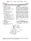
7 F, 04-Feb-133 Document Number: 91265 For technical questions, contact: DOCUMENT IS SUBJECT TO CHANGE WITHOUT NOTICE. THE PRODUCTS DESCRIBED HEREIN AND THIS DOCUMENTARE SUBJECT TO SPECIFIC DISCLAIMERS, SET FORTH AT CHARACTERISTICS (25 C, unless otherwise noted)Fig. 1 - Typical Output Characteristics, TC = 25 CFig. 2 -Typical Output Characteristics, TC = 150 C Fig. 3 - Typical Transfer Characteristics Fig. 4 - Normalized On-Resistance vs. TemperatureIRFR110, Siliconix S13-0171-Rev. F, 04-Feb-134 Document Number: 91265 For technical questions, contact: DOCUMENT IS SUBJECT TO CHANGE WITHOUT NOTICE.
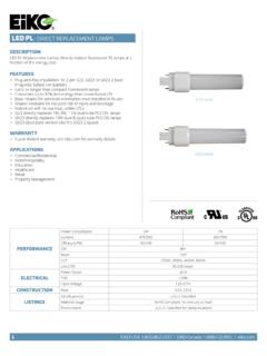
8 THE PRODUCTS DESCRIBED HEREIN AND THIS DOCUMENTARE SUBJECT TO SPECIFIC DISCLAIMERS, SET FORTH AT Fig. 5 - Typical Capacitance vs. Drain-to-Source Voltage Fig. 6 - Typical Gate Charge vs. Gate-to-Source VoltageFig. 7 - Typical Source-Drain Diode Forward VoltageFig. 8 - Maximum Safe Operating AreaIRFR110, Siliconix S13-0171-Rev. F, 04-Feb-135 Document Number: 91265 For technical questions, contact: DOCUMENT IS SUBJECT TO CHANGE WITHOUT NOTICE. THE PRODUCTS DESCRIBED HEREIN AND THIS DOCUMENTARE SUBJECT TO SPECIFIC DISCLAIMERS, SET FORTH AT 9 - Maximum Drain Current vs. Case TemperatureFig.
9 10a - Switching Time Test CircuitFig. 10b - Switching Time Waveforms Fig. 11 - Maximum Effective Transient Thermal Impedance, Junction-to-CaseFig. 12a - Unclamped Inductive Test CircuitFig. 12b - Unclamped Inductive WaveformsPulse width 1 sDuty factor % V+-VDSVDDVDS90 %10 %VGStd(on)trtd(off) +-VDDA10 VVar y tp to obtainrequired IASIASVDSVDDVDStpIRFR110, Siliconix S13-0171-Rev. F, 04-Feb-136 Document Number: 91265 For technical questions, contact: DOCUMENT IS SUBJECT TO CHANGE WITHOUT NOTICE. THE PRODUCTS DESCRIBED HEREIN AND THIS DOCUMENTARE SUBJECT TO SPECIFIC DISCLAIMERS, SET FORTH AT 12c - Maximum Avalanche Energy vs.
10 Drain CurrentFig. 13a - Basic Gate Charge WaveformFig. 13b - Gate Charge Test CircuitQGSQGDQGVGC harge10 F50 k 12 VCurrent regulatorCurrent sampling resistorsSame type as +-IRFR110, Siliconix S13-0171-Rev. F, 04-Feb-137 Document Number: 91265 For technical questions, contact: DOCUMENT IS SUBJECT TO CHANGE WITHOUT NOTICE. THE PRODUCTS DESCRIBED HEREIN AND THIS DOCUMENTARE SUBJECT TO SPECIFIC DISCLAIMERS, SET FORTH AT 14 - For N-ChannelVishay Siliconix maintains worldwide manufacturing capability. Products may be manufactured at one of several qualified locations.