Transcription of power over ethernet - Cisco
1 CHAPTER16-1 Cisco IOS Software Configuration Guide, Release power over ethernet Support This chapter describes how to configure power over ethernet (PoE) support on the Catalyst 6500 series additional information about Cisco Catalyst 6500 Series Switches (including configuration examples and troubleshooting information), see the documents listed on this page: Participate in the Technical Documentation Ideas forum This chapter consists of these sections: Understanding PoE, page 16-1 Configuring PoE Support, page 16-4 NoteFor information about switching modules that support PoE, see the Release Notes for Cisco IOS Release publication at this URL: Understanding PoE These sections describe PoE: Device Roles, page 16-2 PoE Overview, page 16-2 CPD-Based PoE Management, page 16-3 Inline power IEEE power Classification Override, page 16-3 LLDP Inline power Negotiation for PoE+ (IEEE ), page 16-416-2 Cisco IOS Software Configuration Guide, Release 16 Configuring power over ethernet SupportUnderstanding PoEDevice Roles power sourcing equipment (PSE) A device that provides power through a twisted-pair ethernet connection.
2 The switch, through switching modules equipped with power over ethernet (PoE) daughtercards, functions in the PSE role. Powered device (PD) A device powered by a PSE (for example, IP phones, IP cameras, and wireless access points). NoteNot all PoE-capable devices are powered from the switch. There are two sources of local power for PoE-capable devices: A power supply connected to the device. A power supply through a patch panel over the ethernet connection to the device. When a locally powered PoE-capable device is present on a switching module port, the switching module itself cannot detect its presence. If the device supports CDP, the supervisor engine can discover a locally powered PoE-capable device through CDP messaging with the device. If a locally powered PoE-capable device loses local power , the switching module can discover and supply power to the IP phone if the inline power mode is set to auto.
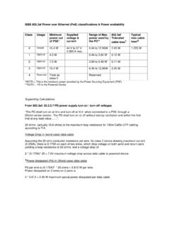
3 PoE Overview Cisco PoE daughtercards support one or more PoE implementation: IEEE standard, shown in Cisco Feature Navigator as PoE Plus (PoE+, PoEP) support . Supported only with the PoE daughtercard on the WS-X6148E-GE-45AT switching module. With Release (33)SXJ2 and later releases, these features are supported for IEEE class 4 PDs: Class 4: W at the PSE ( W to W at the PD). Optionally, LLDP Inline power Negotiation for PoE+. With releases earlier than Release (33)SXJ2, maximum W at the PSE (ePoE for 45 ports maximum). IEEE standard. Supported with the WS-F6K-48-AF PoE daughtercard and the PoE daughtercard on the WS-X6148E-GE-45AT switching module. With Release (33)SXH2 and later releases, maximum W at the PSE. With releases earlier than Release (33)SXH2, maximum W at the PSE.
4 The IEEE PoE standard defines a method to sense a PD and to immediately classify the power requirement of the PD into these per port power ranges at the PSE: Class 0: Up to W ( W at the PD; default classification) Class 1: Up to 4 W ( W at the PD) Class 2: Up to 7 W ( W at the PD) Class 3: Up to W ( W at the PD) Cisco prestandard inline power 10 W at the PSE. 16-3 Cisco IOS Software Configuration Guide, Release 16 Configuring power over ethernet SupportUnderstanding PoEWith a PoE daughtercard installed, a switching module can automatically detect and provision a PoE-capable device that adheres to a PoE implementation supported by the PoE daughtercard. The switching module can supply power to devices supporting other PoE implementations only through manual configuration.
5 Only a PD connected directly to the switch port can be powered from the switch. If a second PD is daisy-chained from the PD that is connected to the switch port, the second PD cannot be powered by the switch. Each PD requires power to be allocated from the chassis power budget. Because each PD can have unique power requirements, more devices can be supported if the system s power management software can intelligently allocate the necessary power on a per-port basis. You can configure ports to allocate power at a level based on the following: If a PD is detected, with auto mode configured: Information sensed from the device A default level A configured maximum level Whether or not a PD is present on the port, with static mode configured: A default level A configured level CPD-Based PoE Management When a switching module port detects an unpowered PD, the default-allocated power is provided to the port.
6 When the correct amount of power is determined through CDP messaging with the PD, the supervisor engine reduces or increases the allocated power , up to the hardware limit of the installed PoE daughtercard. CautionWhen a PD cable is plugged into a port and the power is turned on, the supervisor engine has a 4-second timeout waiting for the link to go up on the line. During those 4 seconds, if the IP phone cable is unplugged and a network device is plugged in, the network device could be damaged. We recommend that you wait at least 10 seconds between unplugging a network device and plugging in another network power IEEE power Classification Override The IEEE standard contains no provision for adjustment of the power allocation. PDs that support CDP can use CDP to override the IEEE power classification.
7 With the WS-F6K-48-AF PoE daughtercard or the PoE daughtercard on the WS-X6148E-GE-45AT switching module, Release (33)SXH and later releases support these inline power IEEE power classification override features: power use measurement The ability to accurately measure the power provided by the port to the powered device. power policing The ability to monitor power usage on a port. 16-4 Cisco IOS Software Configuration Guide, Release 16 Configuring power over ethernet SupportConfiguring PoE SupportWith power measurement and policing, you can safely override the IEEE power classification of a device that requires a power level at the lower end of its IEEE power classification range. PoE monitoring and policing compares the power consumption on ports with the administrative maximum value (either a configured maximum value or the port s default value).
8 If the power consumption on a monitored port exceeds the administrative maximum value, the following actions occur: A syslog message is issued. The monitored port is shut down and error-disabled. The allocated power is freed. LLDP Inline power Negotiation for PoE+ (IEEE ) With the PoE daughtercard on the WS-X6148E-GE-45AT switching module, Release (33)SXJ2 and later releases support IEEE LLDP PoE power negotiation, which supports additional negotiation that can reduce power usage. Note Enabled by default. The LLDP TLV used is DTE power -via-MDI TLV. When a PD that performs power negotiation using multiple protocols (CDP and LLDP ) is connected to a switch, the switch locks to the first protocol packet (CDP or LLDP) that contains the power negotiation TLV. If you need to use any single protocol for power negotiation each time, you must administratively disable the other power negotiation protocols on the switch interface.
9 See this publication for other the Link Layer Discovery Protocol (LLDP) configuration procedures: Configuring PoE Support Displaying PoE Status, page 16-5 Configuring Per-Port PoE Support, page 16-5 Configuring PoE power Priority, page 16-7 Configuring PoE Monitoring and Policing, page 16-8 Disabling LLDP power Negotiation (IEEE ), page 16-8 NoteThe switch supports PoE only on Layer 2 switchports. 16-5 Cisco IOS Software Configuration Guide, Release 16 Configuring power over ethernet SupportConfiguring PoE SupportDisplaying PoE StatusThis example shows how to display the PoE status on switch: Router# show power auxiliary system auxiliary power mode = onsystem auxiliary power redundancy operationally = redundantsystem primary connector power limit = Watts ( Amps @ 42V)system auxiliary connector power limit = Watts ( Amps @ 42V)system primary power used = Watts ( Amps @ 42V)system auxiliary power used = Watts ( Amps @ 42V)
10 Inline Inline-Pwr Inline-Pwr VDB Pwr-Limit Used-Thru-Pri Used-Thru-Aux Aux-PwrSlot Card-Type Watts A @42V Watts A @42V Watts A @42V Capable---- ------------------ ------- ------ ------- ------ ------- ------ -------2 WS-F6K-48-AT Yes4 WS-F6K-48-AT Yes---- ------------------ ------- ------ ------- ------ ------- ------ -------Totals: Configuring Per-Port PoE Support To configure per-port PoE support, perform this task: When configuring inline power support with the power inline command, note the following information: To configure auto-detection of a PD and PoE auto-allocation, enter the auto keyword.