Transcription of POWER RELAY - Fujitsu
1 1 POWER RELAY1 POLE - 8A Medium Load ControlJS Series FEATURES UL class B (130 C) coil wire insulation 1 form A (SPST-NO) or 1 form C (SPDT) contact Low profile and space saving Height: mm - Mounting space: 290 mm2 High sensitivity in small packageOperating POWER 110 to 140 mWNominal POWER 220 to 290 mW High insulation in small packageInsulation distance : mm (between coil and contacts)Dielectric strength : 5,000 VACS urge strength : 10,000 V Plastic materialsUL 94 flame class V-0 UL CTI level class 2 Plastic sealed type Various contact material options RoHS compliant (Please see page 6 for more information) Part Numbers[Example]JS-12MF-KT-V3*-RW(a)(b)( c)(d)(e)(f)(g)(h)(a) RELAY typeJS: JS series(b)Contact rated voltage12: (Coil rating table at page 3)(c)Coil configurationNilM: 1 form C (SPDT): 1 form A (SPST-NO)(d)Contact materialDFN: Silver nickel: Gold flash silver nickel: Gold flash(e)EnclosureK: Plastic sealed type(f)ConstructionNilT: : (only JS-MN)(g)Gold platingNilV3V1: Standard ( gold flash with Nil, N and F contact): gold plating for lower current applications (available with Nil and N contact, not available for T, type): gold plating for lower current applications (avaialble with N contact, not available for T, 5,0mm type)(h)Special typeNilRW: Standard: Reflow capable (through hole reflow) (not available for V1, V3)Note: Actual marking omits the hyphen (-) or (*)*: V3 is marked at different position on the : Ordering code: JS-12F Actual marking: JS12F-K2JS Series SpecificationsItemJS-( )F/N-KJS-( )D-KJS-( )N-K-V1JS-( )N-K-V3 Remarks / conditionsContact dataConfiguration1 form A (SPST-NO), 1 form C (SPDT) Au Plated-1 Au Plated3 Au PlatedMaterialSee partnumber 6 VDC, 1 AContact rating8A, 250 VAC / 24 VDCR esistiveMax.
2 Carrying current10 AMax. switching voltage400 VAC / 300 VDC (-RW; 400 VAC / 150 VDC)Max. switching power2000VA / 192 WMin. switching load *1100 mA, 5 VDC10 mA, 5 VDCCoilRated POWER (20oC)220 - 290mWOperate POWER (20oC)110 - 140mWOperating temperature range-40 C ~ +85 C (at rated voltage)No frostTiming dataOperateMax. 10mswithout bounceReleaseMax. 5mswithout bounce, no diodeLifeMechanicalMin. 20 x 10 operationsElectrical (resistive)AC contact ratingMin. 50 x 103 operations (AgSnO2)Min. 20 x 103 operations (AgNi)At rated loadDC contact ratingMin. 50 x 103 operations (AgSnO2)Min. 20 x 103 operations (AgNi)At rated loadInsula-tionInsulation resistanceMin. 1000M at 500 VDCD ielectric strengthOpen contacts1000 VAC (50/60Hz), 1 minuteCoil contact5000 VAC (50/60Hz), 1 minuteSurge strengthCoil to contacts10000V / x 50 s standard waveClearance8mmCreepage8mmEN61810-1, VDE0435 Voltage250 VPollution3 Material groupIII aCategoryC / 250V (reference voltage) (VDE 01106)OtherVibration resis-tanceMisoperation10Hz ~ 55Hz ~ 10Hz single amplitude ~ 55Hz ~ 10Hz single amplitude resis-tanceMisoperationMin.
3 100m/s (11 1ms)Direction X, Y, Z, contact ON/OFF total 36 timesEnduranceMin. 1,000m/s (6 1ms)Direction X, Y, Z, contact OFF total 18 timesDimensions / x x mm / approx. sealed*1: Minimum switching loads mentioned above are reference values. Please perform the confirmation test with actual load before production since reference values may vary according to switching frequencies, environmental contions and expected reliability Series Coil DataCoil codeRated Coil Voltage(VDC)Coil Resistance +/-10%( )Must Operate Voltage* (VDC)Must Release Voltage* (VDC)Rated POWER (mW) , , , , : All values in the table are valid at 20oC and zero contact current, unless otherwise specified.*: Specified operated values are valid for pulse wave : Please use at rated coil voltage. Please refer to characteristic data and set up adequate voltage in case of use at over shall be taken on the heat generated on PC board when maximum carrying current exceeds 10A.
4 Please perform the confirmation test with actual conditions. Safety StandardsTypeComplianceContact ratingULUL 508 Flammability: UL 94-V-0 (plastics)Contact material: Nil, END, FFile No. E 561408A 24 VDC (resistive) 100k8A, 250 VAC (resistive) 100k10A, 30 VDC (resistive)10A, 250 VAC (resistive)1/4HP, 125 VAC / 250 VAC1/3HP, 125 VAC1/2HP, 250 VACP ilot duty: C150, B300 Pilot duty: , 250 VDC8A 24 VDC (resistive) 100k8A, 250 VAC (resistive) 100k10A, 30 VDC (resistive)10A, 250 VAC (resistive)1/4HP, 125 VAC / 250 VAC1/3HP, 125 VAC1/2HP, 250 VACP ilot duty: A300, B300C150, R3008A, 24 VDC resistive8A, 250 VAC No. 14 File No. LR 35579 VDEIEC/EN61810-1EN60335-1 ; ; ; ; ; ; ; ; Appendix C8A 250 VAC (cos =1)8A 24 VDC (L/R=0ms)JS-( )D-K, JS-( )F-K:6A, 250 VAC, (cos =1)8A, 24 VDC (L/R=0ms)JS-( )MD-K, JS-( )MF-K:8A, 240 VAC (cos =1)8A, 24 VDC (L/R=0ms) 30 VDC/250 VAC (except -V3 type)4JS Series Characteristic Data (Reference)* Characteristic data is not guaranteed value but measured values of samples from production Series Characteristic Data (Reference)* Characteristic data is not guaranteed value but measured values of samples from production Series Dimensions DimensionsJS-M-KJS-KJS-MN-KT* Dimensions of the terminals do not include thickness of pre-solder.
5 Schematics(BOTTOM VIEW)JS-M-KJS-KJS-MN-KT PC Board Mounting Hole Layout(BOTTOM VIEW)JS-M-KJS-KJS-MN-KT( ): Reference value Unit: mm* Tolerance of PC board mounting hole layout : unless otherwise -pre solder4 -pre solder(Spring terminal)(Coil terminal)10 + ( ) -pre solder5 -pre solder(Spring terminal)(Coil terminal)10 + ( ) -pre solder4 -pre solder(Spring terminal)(Coil terminal)10 + ( ) mark1354 NOCOMO rientation mark12354 NONCCOMO rientation - - ( ) ( ) - - ( ) ( )52 - - ( ) ( )7JS SeriesGENERAL INFORMATION1. ROHS Compliance All relays produced by Fujitsu Components are compliant with RoHS directive 2011/65/EU including amend-ments. Use of Cadmium in electrical contacts is exempted as per Annex III of the RoHS directive 2011/65/EU. Please consider expiry date of exemption. Relays with Cadmium containing contacts are not to be used for new designs. All relays are lead-free. Please refer to Lead-Free Status Info for older date codes at: Characteristic data is not guaranteed values, but measured values of samples from production Recommended lead free solder condition Lead free solder plating on RELAY terminals is , unless otherwise specified.
6 This material has been verified to be compatible with PbSn assembly process. Recommended solder for assembly: NOTES FOR REFLOW SOLDERING Temperature shall be measured at PC board upper surface. Temperature at PC board upper surface may be changed depending on size of PC board, components mounted on the PC board and/or heating method. Please perform the confirmation test with your actual PC boards. This reflow solder condition is applicable only for reflow-capable relays. Do not reflow reflow-incapable relays. Recommended solder for assembly: Moisture Sensitivity Moisture Sensitivity Level standard is not applicable to electromechanical relays, unless otherwise indicat-ed. 4. Tin Whiskers Dipped SnAgCu solder is known as presenting a low risk to tin whisker development. No considerable length whisker was found by our in house highly recommend that you confirm your actual solder conditionsFlow Solder Condition:Pre-Heating: maximum 120 C within 90 : dip within 5 sec.
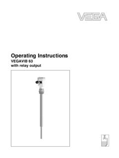
7 At 255 C 5 C solder bathRelay must be cooled by air immediately after solderingSolder by Soldering Iron:Soldering Iron: 30-60 WTemperature: maximum 350-360 CDuration: maximum 3 ( C) 120 30 sec.(T ime)Pre-heatingAir coolingPeaktemperature: CRecommended reflow soldering profileIRS (infrared reflow soldering) 8JS SeriesFujitsu Components International Headquarter Offices 2017 Fujitsu Components Europe All rights reserved. All trademarks or registered trademarks are the property of their respective owners. The contents, data and information in this datasheet are provided by Fujitsu Component Ltd. as a service only to its user and only for general information use of the contents, data and information provided in this datasheet is at the users own risk. Fujitsu has assembled this datasheet with care and will endeavor to keep the contents, data and information correct, accurate, comprehensive, complete and up to date.
8 Fujitsu Components Europe and affiliated companies do however not accept any responsibility or liability on their behalf, nor on behalf of its employees, for any loss or damage, direct, indirect or consequential, with respect to this datasheet, its contents, data, and information and related graphics and the correctness, reliability, accuracy, comprehensiveness, usefulness, availability and completeness thereof. Nor do Fujitsu Components Europe and affiliated companies accept on their behalf, nor on behalf of its employees, any responsibility or liability for any representation or warrant of any kind, express or implied, including warranties of any kind for merchantability or fitness for particular use, with respect to these datasheets, its contents, data, information and related graphics and the correctness, reliability, accuracy, comprehensiveness, usefulness, availability and completeness thereof. Rev. October 25th, 2017 JapanFUJITSU COMPONENT LIMITEDS hinagawa Seaside Park Tower 19F,12-4, Higashi-shinagawa 4-chome, Shinagawa-ku,Tokyo,140-0002, JapanTel: (81-3) 3450-1682 Fax: (81-3) 3474-2385 Email: and South AmericaFUJITSU COMPONENTS AMERICA, INC2290 North First Street, Suite 212 San Jose, CA 95131, USATel: (1-408) 745-4900 Fax: (1-408) 745-4970 Email: COMPONENTS EUROPE 252132 WV HoofddorpNetherlandsTel: (31-23) 5560910 Fax: (31-23) 5560950 Email: PacificFUJITSU COMPONENTS ASIA, Pasir Panjang Road#01-01 Citilink Warehouse ComplexSingapore 118529 Tel: (65) 6375-8560 Fax: (65) 6273-3021 Email: ELECTRONIC COMPONENTS (SHANGHAI) CO.
9 , 4306, InterContinental Center100 Yu Tong Road, Shanghai 200070, ChinaTel: (86-21) 3253 0998 Fax: (86-21) 3253 0997 Email: KongFUJITSU COMPONENTS HONG KONG CO., LTDUnit 506, Inter-Continental Granville Road, Tsim Sha Tsui, Kowloon,Hong KongTel: (852) 2881-8495 Tex: (852) 2894-9512 Email: COMPONENTS KOREA LIMITEDA lpha Tower #403, 645 Sampyeong-dong, Bundang-gu, Seongnam-si, Gyeonggi-do, 13524 Korea Tel: (82) 31-708-7108 Fax: (82) 31-709-7108 Email.