Transcription of Power Supply Noise Reduction - Designer’s Guide
1 The Designer s Guide Communitydownloaded from 2019, Kenneth S. Kundert All Rights Reserved1 of 12 Version 4, January 2004An introduction into the basics of Power Supply Noise Reduction using Supply bypassingand TermsPower Supply Noise , Supply ringing, Supply damping, bypass capacitors, dcap capaci-tors, decoupling capacitors, bypass versus decoupling. Originally written in 1979, with modest updates in 1981 and updated on March 10, 2019. You can find the most recent version at Contact the author via e-mail at to make copies, either paper or electronic, of this work for personal or classroom useis granted without fee provided that the copies are not made or distributed for profit or commer-cial advantage and that the copies are complete and unmodified.
2 To distribute otherwise, to pub-lish, to post on servers, or to distribute to lists, requires prior written Supply Noise ReductionKen KundertDesigner s Guide Consulting, Supply Noise ReductionIntroduction2 of 12 The Designer s Guide IntroductionMany of the problems that appear out of Murphy s box upon transforming a design from the mythical world of textbooks and SPICE to the real world emanate from the non-ideal Power Supply . Real Power supplies can cause Noise and spurious oscillations that can force the designer into a frustrating glitch hunt. Rules of thumb can usually be applied successfully to simple problems, but a little understanding and forethought will usually provide clean solutions to even the more obscure problems.
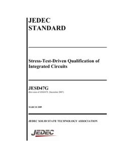
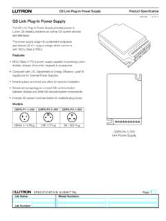
3 With this paper, I hope to provide the understanding of some of the dynamics of Power distribution. The fore-thought is up to DefinitionsBypassing and decoupling are often poorly understood and poorly applied. Many designers believe bypassing and decoupling are synonymous. They are not; they are dis-tinct concepts and each is a solution to a different problem (see Figure 1).Bypassing is the Reduction of high frequency current flow in a high impedance path byshunting that path with a bypass, usually a capacitor (in this case, Cbyp). Bypassing isused to reduce the Noise current on Power Supply is the isolation of two circuits on a common line. The decoupling network isusually a low pass filter and the isolation is rarely equal in both directions.
4 Decouplingis used to prevent transmission of Noise from one circuit to another. In the figure abypass capacitor, Cbyp, is shown along with the decoupling circuit, Ldec and Cdec. This isbecause in practice bypassing is always used when circuits require bypassing, not decoupling. Using decoupling techniques toaccomplish bypassing will give disappointing, if not disastrous, results. Completeunderstanding of both concepts is vital. We begin with 1 Bypassing and sensitive circuitsBypassingPower Supply Noise Reduction3 of 12 The Designer s Guide BypassingDue to the finite bandwidth of all voltage regulators, their output impedance increases with frequency. This can be modeled as an inductor in series with the output.
5 Typical values lie between 1 H and 2 H for a linear three terminal regulator. The output impedance of switching regulators varies widely and should be measured for each case. The interconnecting leads add about 20 nH per inch. When an active load is connected, the time varying current demand creates a Noise voltage across these inductors. This Noise voltage can be reduced in only two ways: reduce the rate of change of the current (di/dt) passing through the inductor, or reduce the inductance. Bypassing reduces the rate of change of the current through the bypassing, a secondary, high frequency low impedance path (a capacitor) is providedfor the varying currents from the load that shares as little inductance as possible with thepower Supply leads.
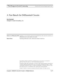
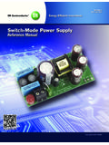
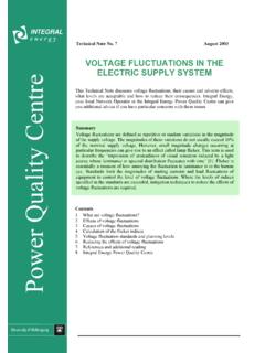
6 The key to successful bypassing is to properly determine the flowof current from a load and to Supply a return path that is not common with any other partof the circuit (see Figure 2). The bypass path must be a significantly lower impedance atthe frequency of interest than the Power Supply leads. It is always better to use manysmall parallel capacitors than one large one. This is because the equivalent series induc-tance does not vary significantly with capacitance. The parallel bypass paths achievedwith the small capacitors results in a much lower total must be taken when determining the return current path. It is often not obvious atfirst glance as demonstrated in Figure 3. In this case the standard bypassing is applied,which causes a current to flow in the ground and Supply leads, which generates a noisevoltage.
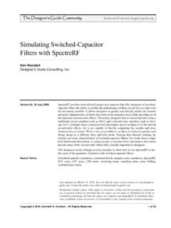
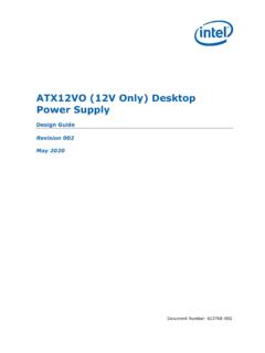
7 In Figure 4, this situation is remedied. 4 Reducing InductanceAs mentioned above, one way to reduce the Noise voltage developed in the Power sup-ply inductance is to reduce that inductance. To reduce the inductance of a linear regula-tor, you can either increase its bandwidth or decrease its open loop output are really not options unless you design your own regulator. There are also twomethods for decreasing the inductance of the Power Supply bus. One is to decrease itsself inductance, and the other is to increase the mutual coupling to its return path. AFIGURE 2 Proper +V CbypPower Supply Noise ReductionReducing Inductance4 of 12 The Designer s Guide s self inductance can be reduced by decreasing its length, increasing its radius (asmall effect) or running multiple isolated benefit of increased mutual coupling is illustrated in Figure 5.
8 The couplingbetween the forward and return paths cause the voltage generated in the self-inductanceof one path to be cancelled by the voltage induced from the coupling from the otherpath. With perfect coupling also comes perfect cancellation and zero effective induc-tance. To increase the mutual coupling between paths requires decreasing the distanceFIGURE 3 Improper bypassing. Bypass current runs through shared Supply 4 Proper 5 Cancellation of inductance using mutual +InGndCbypV+InGndCbyp+ + + + Mutual CouplingLoadForward PathReturn PathDecouplingPower Supply Noise Reduction5 of 12 The Designer s Guide them or increasing their width. It is best to place the forward and return pathsas close as possible.
9 Using Supply planes, as opposed to Supply traces, along with aground plane, causes this to happen using two layer boards, it is difficult to lay out Power Supply planes. The secondbest technique is to use a Power grid combined with a ground plane. This reduces theself inductance of the Supply by running many isolated traces to the load. This techniquecan be very successfully applied on digital boards. On analog boards, even this is diffi-cult to do, especially when isolation between circuits is required. In this case, the pre-ferred method is to structure the Supply Cdec like a tree. This minimizes the length, andhence the inductance, of the Supply Cdec. Avoid long serial, or daisy chained powersupply DecouplingWhen it is desired to isolate one circuit from the Noise of another, you should reduce theamount of shared Supply trace between them.
10 If that is not sufficient, decoupling shouldbe used. Decoupling decreases Noise transmission in two ways (see Figure 6). First,since decoupling always consists of a high impedance element in series with the supplyline, it assists the bypassing; assuring that the Noise current will flow through the lowimpedance bypass element rather than the Supply . Second, it acts as a low pass filter sothat the high-frequency content of any current that does pass through the series elementwill be attenuated, making it more likely that the regulator will be able to react and keepthe Supply voltage series element may either be a resistor (when DC voltage drop is not a problem), oran inductor, or both. Sometimes even a parallel resonant tank circuit may be used if thenoise is concentrated at one choosing component values for a decoupling network, two parameters are impor-tant.